Modern tractors in horticulture
Basic terms
The basic machines used in plant cultivation, one of the agricultural sectors, are the agricultural power machines, or tractors, as they are called in every day language. These tractors, depending on their application, are in many different versions available.
Plant cultivation can be further subdivided into three areas:
-
Plant cultivation on arable land: food, fodder and industrial crops.
-
Horticulture: fruit, vegetable, and wine growing.
-
Grassland management.
The law on arable land sets forth different categories of cultivation sectors according to their use, which correspond to the basic forms and methods of utilizing land (Table 1.1).
|
Cultivation sector |
||
|
Arable land |
Agricultural land |
Crop land |
|
Garden |
||
|
Orchard |
||
|
Grapes |
||
|
Grass |
||
|
Forest |
||
|
Afforested area |
||
|
Marsh |
||
|
Fish pond |
||
|
Land taken out of cultivation |
||
Table 1.1 Agricultural land and the meaning of crop land
In terms of the machines used in horticultural cultivation, we may distinguish between plantations and gardens.
A plantation is established at a permanent location for the purpose of long-term cultivation. Whether to establish a plantation is a decision to be made for the long-term. The plantation’s characteristics are that (i) it is planted for many years and (ii) the row and root distance of the plants is determined and fixed for several years. The row distance must be such that it allows the machines to move freely between the rows (Figure 1.1). These are usually arboreal plants (with woody stalk). Consequently, they bear the mechanical effects of the cultivation well.
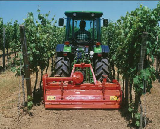
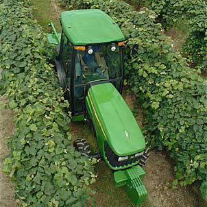
Figure 1.1 Machines moving between the rows
The following is a list of the various plantation types.
-
Fruit tree: apple, pear, peach, cherry, sour-cherry, plum, etc.
-
Hedge: grapes, hop.
-
Bush: berries (raspberry, bramble, etc.).
-
Intensive: for example, modern orchards.
-
Tree nursery: growing propagating material.
-
Planted forest: for example, energy plantation.
Gardens are, for example, the horticultural vegetable cultures.
Their characteristics are:
-
Cultures (from seed sown or transplanted): herbaceous, low height,
-
row spacing is fixed.
-
Row spacing is as big as required for the tractor’s wheels to pass between them (Figure 1.2).
-
Their height allows the tractor (and its implements) to move above the rows (Figure 1.3).
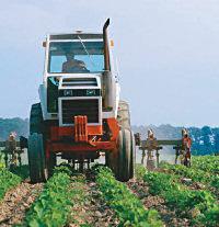
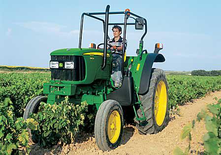
Figure 1.2 Tractor moving above Figure 1.3 Vegetable cultivation
the plants
Classification of tractors
Tractors may be classified according to many different criteria (Table 1.2). The individual classification criteria interrelate, since, for example, universal tractors, are equipped with different drive systems.
|
Main classification criteria |
Names used |
Markings in use |
|
|
Size / capacity / according to tractive force |
heavy |
||
|
semi-heavy |
|||
|
light |
|||
|
Running component |
tire |
||
|
caterpillar |
|||
|
rubber belt |
|||
|
Power transmission |
mechanic |
||
|
hydraulic (hydrostatic) |
|||
|
mixed (power-split) |
power-split |
||
|
Driving system |
front axle drive |
FWD / 2WD |
|
|
front axle auxiliary drive |
FWA / MFD |
||
|
rear axle drive |
RWD / 2WD |
||
|
all-wheel drive |
4WD / AWD / 4x4 |
||
|
caterpillar / rubber belt |
|||
|
Gear shift |
sliding gear |
||
|
synchromesh |
|||
|
under load, adjustable partially or in the full range |
semi-power shift |
||
|
full-power shift |
|||
|
CVT |
|||
|
IVT |
|||
|
Hydrostatic, continuous or infinitely variable transmission |
|||
|
Steering system |
front-wheel |
2WS |
|
|
all-wheel |
4WS / AWS |
||
|
joint / articulated |
|||
|
turning brake steering |
|||
|
skid steering |
skid-steer |
||
|
Application |
tilling tractor |
||
|
universal tractor |
|||
|
special tractors |
horticultural tractor |
||
|
tool carrier |
|||
|
plantation tractor |
|||
|
gantry |
|||
|
lawn mower (tractor) |
|||
|
forestry tractor |
|||
|
communal tractor |
|||
Table 1.2 The main classification criteria of agricultural tractors and their names used
Horticultural tractors
Compared to the universal tractors, horticultural tractors have special structural requirements in order to be suitable for the various utilization areas. The structural requirements are different in each cultivation sector. The following are the most important requirements where recently significant innovations and developments have occurred:
-
Narrow structural design suitable for moving between the rows.
-
Adjustable wheel track and clearance enabling movement above the rows.
-
Several gears and continuous or infinitely variable transmission.
-
Easy turning: small turning radius to enable the tractor to turn at the end of the rows and, in case of lawn mowers, to avoid obstacles.
-
Increased stability, for example, on sloping areas.
-
Universality: front/back attachment possibilities (3-point hitch, PTO, hydraulic attachment).
-
Universality: possibility for applying a wide variety of adapters.
The following are some modern solutions meeting the above requirements:
Steering:
- SuperSteer (New Holland)
- Zero Turn
- Synchro Steer (Cub Cadet)
Stability: - Kombi Trak/Terra Trac (Aebi)
Communal tractors: - KommunalTrak (KT), MFH (Aebi)
Universality: - Tecno (Avant)
Plantation tractors
The so-called “plantation tractors” (basically in the universal tractors’ order of magnitude) move between the rows planted in fixed locations for many years. Therefore, narrow body design and narrow wheel track are the basic requirements (Figure 1.4).
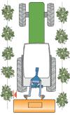
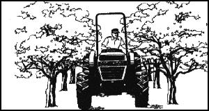
Figure 1.4 Application of plantation tractors
The task of the plantation tractors is to operate machines for:
-
Planting the plantation (for example, building the trellis, pit drilling, post driving).
-
Cultivation work (for example, shallow tilling, disk harrowing, rotary tilling, chopping of trimmings and their incorporation in the soil, etc.
-
Treatment of the plantation plants (for example, hedge trimming, crown formation, energy supplying for mechanical pruning).
-
Plant protection (plant treatment, irrigation, spraying of hedges and limbs.
-
Harvesting,
-
Facilitation of fruit picking, for example, operation of tree shakers.
-
Towing of manual picking implements.
-
Transportation of material during fruit picking, such as depositing empty crates, transporting pickers, produce, and full containers, in each case to the required location.
-
The characteristics of the plantation tractor (Figures 1.5 and 1.6) are the following:
-
The tractor’s size must be appropriate for the row distance and the height of the plant,
-
Narrow wheel track: external width ≈ 60cm smaller than the row distance.
-
Gantry: arches over several rows, moves over the plants.
-
Universal tractor: adjustable wheel track for work in horticultural cultures on arable land.
-
Low center of gravity: on slopes, there is danger of rolling over (for example, in vineyards).
-
Increased clearance.
-
Significant climbing capability on slopes.
-
Small turning radius (necessary because of the turn is limited by the row distance).
-
Low ground pressure and small slip, as the tractor must move on the same track for many years, every year.
-
Good visibility: the operator must be able to see the cultivating equipment, taking into account especially narrow row distance and dense foliage.
-
Gentle gear shifting in the cultivation speed range (2-8km/h).
-
Climbing gear (for planting: ≈ 500 m/h).
-
Front and rear hitch system/hydraulic attachment to the driving mechanism of the tools and equipments: possibility to attach many different adapters.
-
Front and rear PTO (with a speed proportionate to the motor’s speed).
-
Comfort conditions and safe work environment (slopes, branches, spraying) for the operator of the tractor.
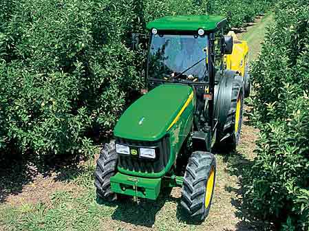
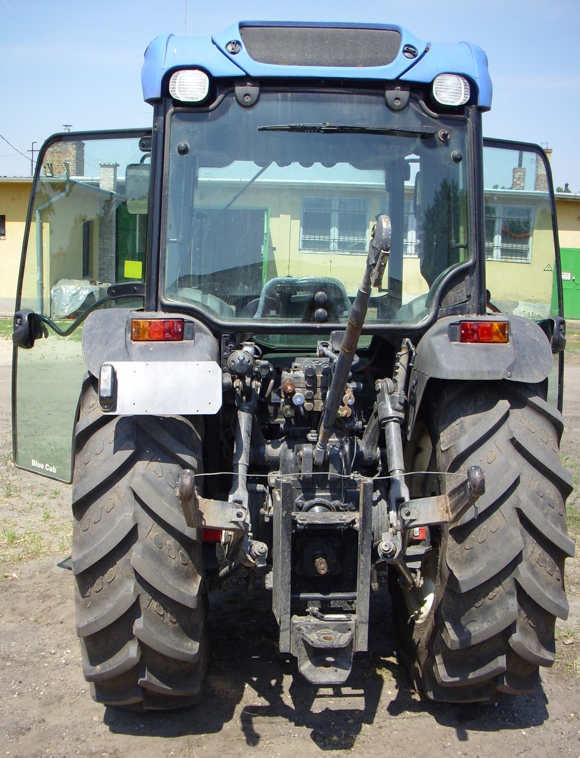
Figure 1.5 Plantation tractor Figure 1.6 Narrow gage track
Adjustable wheel track and big clearance are required for tractors cultivating arable land vegetables.
Steering modern horticultural tractors
SuperSteer
Already in 1992 New Holland patented a new steering system, SuperSteer (Figure 1.7). This steering system allows for a radical decrease in the turning radius (according to manufacturing descriptions, even a 30% decrease) and a shorter turning time (Figure 1.8). At the present, the maximum wheel turning angle is ≈ 55o, since at bigger angles the steered wheels would hit the body of the tractor. With automatic all-wheel drive and a maximum of 75° steering angle, the Supersteer front bridges make even a 3.4m turning radius possible.
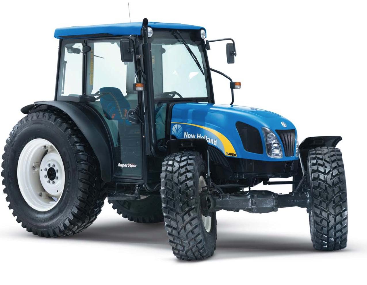
Figure 1.7 New Holland T4050 tractor
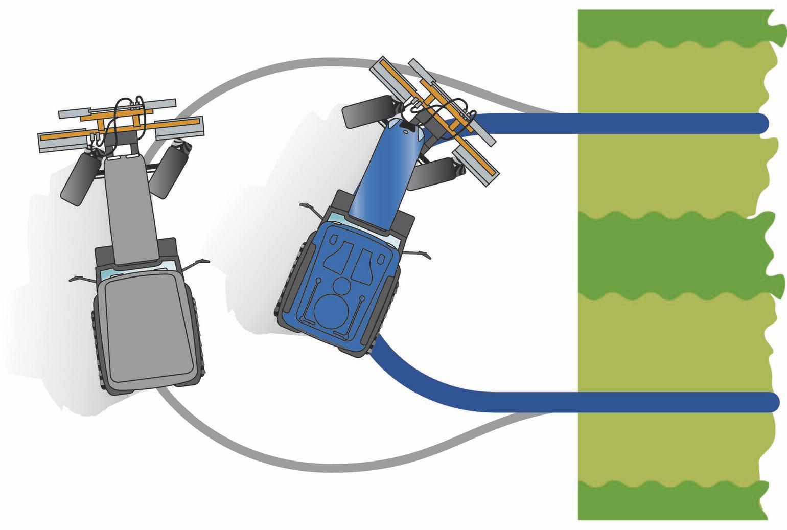
Figure 1.8 Turning circle of SuperSteer steering
The SuperSteer steering system combines bogie and axle stub steering in order to achieve the smallest possible turning circle radius (Figures 1.9 and 1.10).
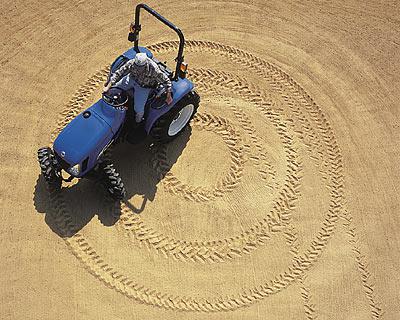
Figure 1.9 Turning circle of SuperSteer
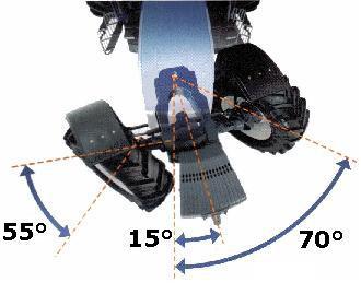
Figure 1.10 Two elements of the steering angle achieved by SuperSteer steering
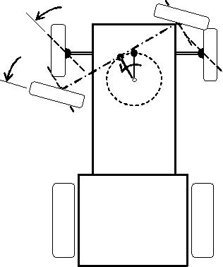
Figure 1.11 The principle of SuperSteer steering
As Figure 1.11 indicates, the steering angle is the sum of the axle stub steering angle (≈ 50…55°) and the bogie style front axle swivel angle (max. ≈ 20°). The novelty of this solution is that the front bridge is located in front of the rotational centre of the “bogie”. This leads to the result that when the “bogie” turns away, the internal, steered wheel moves away from the body of the tractor (decreasing the risk of getting hit), while the external wheel turns in front of the tractor (Figure 1.11).
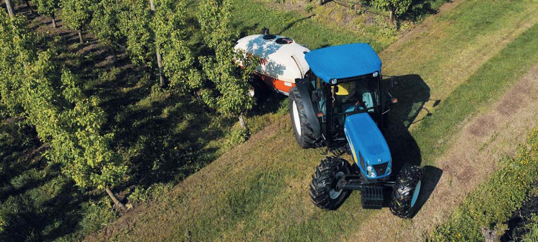
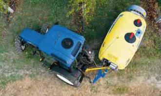
Figure 1.12 NH T4000 turns in the orchard
The advantage of these structural solutions is that the front additional weight is placed directly on the front bridge. Therefore, in case of an all-wheel drive the pulling force is almost constant also during steering. These structural designs have a disadvantage as well. The front 3-point hitch (as it is attached to the front bridge) does not turn away completely; it only follows the turning of the bogie. In addition, the front transmission shaft does not turn at all, which in case of such a significant steering angle may cause the front transmission shaft to hit the other structural parts (Figure 1.13).
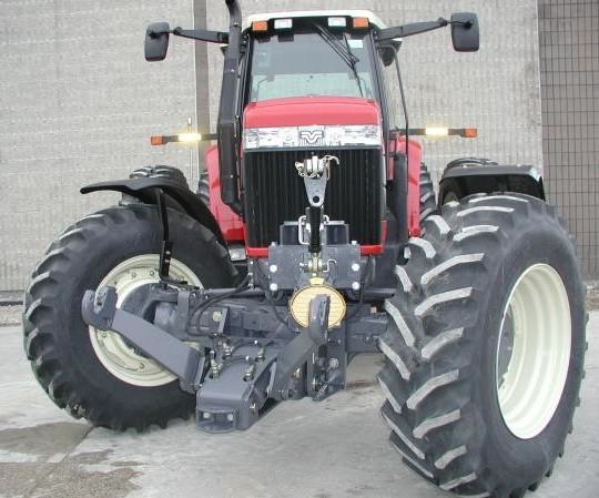
Figure 1.13 The front 3-point hitch and front transmission shaft of SuperSteer
Lawn tractors
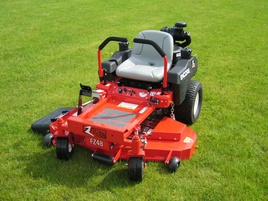
Figure 1.14 Zero-turn lawn mower

Figure 1.15 Frontal self-adjusting wheels
Dumb-waiters, shopping carts, strollers, etc. (but also, for example, armchair rollers) are well-known for the fact that their front wheels always set themselves to the travel direction no matter in which direction they are pushed. This concept is utilized in steering the so-called “zero-turn” lawn tractors which turn in their own length. An important requirement for these tractors is that they should be capable of appropriately approaching and avoiding obstacles (for example, tree trunks, shrubs, bushes, etc.) in order not to leave uncut or untrimmed area.
Their structural design has two main features.
1. The front wheels are not driven. They can make a full 360° turn around the vertical axis. However, it is an important principle that while the axis of the wheels is perpendicular to the vertical rotational axis, in relation to that it is in a deviating position (Figure 1.15).
2. The rear wheels do not turn (they have a fixed axle) and are driven hydrostatically, independently from each other. It can be observed on Figure 1.14 that the tractor’s operator can adjust with the continuous or infinitely variable transmission and the two joysticks the revolution and even the turning direction of the two rear wheels independently from each other. In case of traditional front-wheel axle stub steering the center of the turning circle is outside of the vehicle on the extension of the axle line of the rear driven wheels. In this case however as the center of the turning circle is the center of the rear fixed axle, with directing the drive, the tractor can even turn in its own length (Figure 1.16). In this latter case, the two rear driven wheels revolve with the same speed, but in contrary direction.
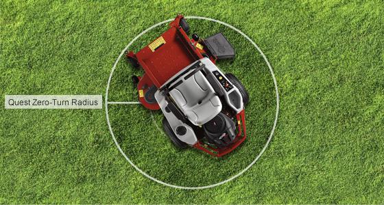
Figure 1.16 The turning circle radius of the tractor turning around its axle
One practical disadvantage of this solution is that in case of sharp turns the front wheels may dig up the soil and damaging the grass specially, sensitive grass. The other disadvantage is the lesser stability on slopes.
Cub Cadet Synchro-Steer
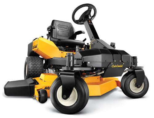
Figure 1.17 Synchro-Steer lawn mowing tractors
The Synchro-Steer steering mechanism patented by Cub Cadet in 2009 is actually the development of tractors turning in their own length mainly for the purpose of solving the above mentioned problems of digging up the soil and grass, and stability (Figure 1.17).
This solution retained the independent drive of the rear wheels, but the steering and the turning of the front wheels are accomplished by the operator turning the steering wheel.
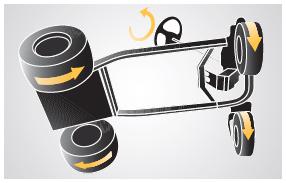
Figure 1.18 The principle of Synchro-Steer
As Figure 1.18 indicates, when the steering wheel is turned, the front wheels turn, simultaneously regulating hydraulically the revolution of the rear driven wheels and, if necessary, their turning direction. Two foot pedals set the travel speed. This design enables the tractor to turn in its own length (Figure 1.19) and, on slopes, allows for a significant increase in stability at the time of turning.
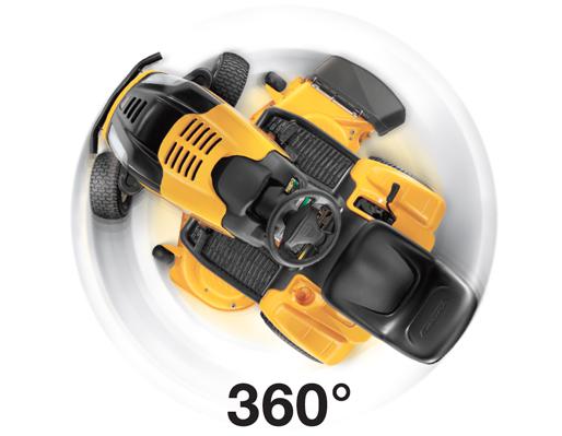
Figure 1.19 Synchro-Steer turning around its axle
Stability of lawn mowing tractors
Lawn tractors must often work on sloping areas such as on hills, on the banks of ditches, on the side of banks or dikes. In these cases, the primary criterion is the stability of the tractor.
In the 1950s an Austrian company, Rasant, developed a special tractor which is suitable primarily for working on alpine pastures (Figure 1.20). Later, the Swiss AEBI bought the company. Since 1976, its TT (TerraTrac) tractor group (with a capacity range between 80-130 HP, 60-95 kW) has been world wide one of the most well known power machine in its category (Figures 1.21, 1.22, and 1.23).
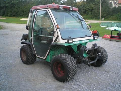
Figure 1.20 Rasant KombiTrak
The main design features are the following:
-
The lowest possible mass center in the interest of increased stability. This is served by the portal-axle style transmission placed between the compensating gear and the wheel, which if compared to the traditional application is used the other way around.
-
Stability is secured by 1:1 ratio of the axle distance to the wheel track
-
Infinitely variable transmission (IVT) and hydrostatic all-wheel drive (4x4, 4WD) to ensure flexibility.
-
All-wheel drive (4WS) to ensure easy turning.
-
Excellent cross-country capability, tires with special moulding, on occasions, double tires.
-
In the interest of operator comfort, operator cab designed with shock absorber, convertible roof, and roll over protection system (ROPS).
-
The front and back 3-point hitch, the PTO, and the hydraulic plugs help universal application.
-
Intelligent field-profile tracking automatics for the lawn mowing adapters mounted on the front hitch.
AEBI TerraTrac
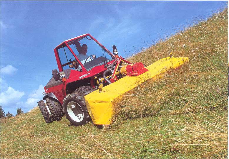
Figure 1.21 TerraTrac TT70
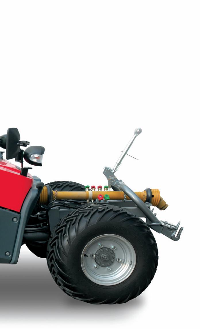
Figure 1.22 Front attachments a), b)
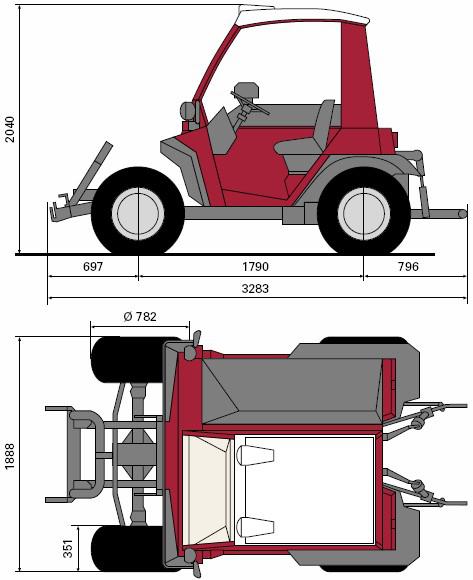
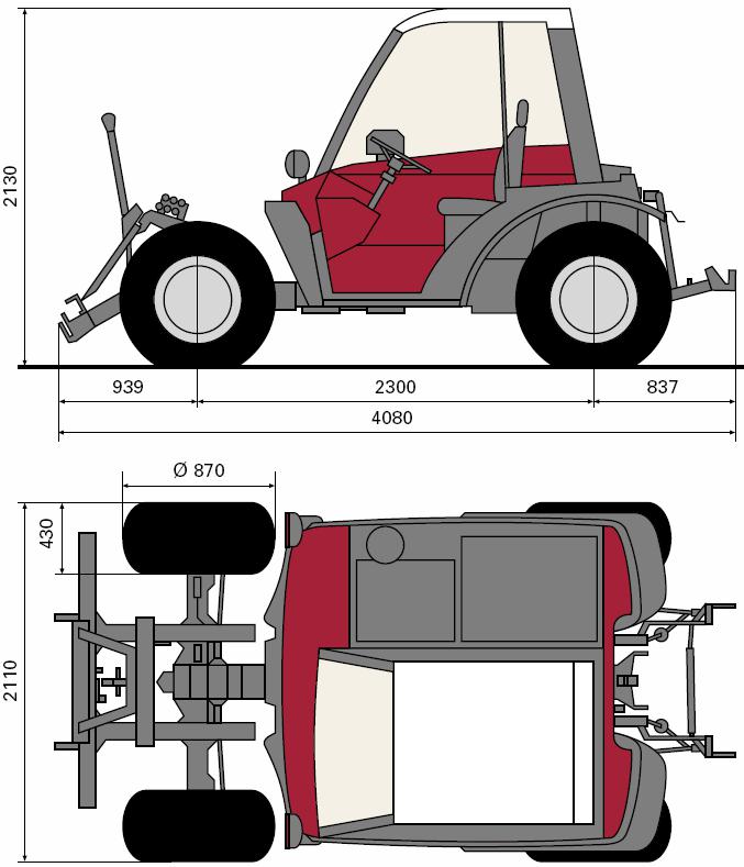
Figure 1.23 Characteristic dimensions of TerraTrac: a) TT75, b) TT270
The TerraTrac drive system (Figure 1.24) consists of a diesel motor located beside the driver seat, a high-pressure hydraulics pump, and a hydro-motor. The middle compensating gear distributes power between the front and the rear axles. On each axle there is a compensating gear for separating the half-axles. The portal style transmission between the compensating gear and the wheels ensures the low center of gravity required for preventing the tractor from rolling over, although this, as a result of the low clearance, reduces cross-country capability. A mechanic distributor mounted on the diesel motor drives the front and rear transmission shafts.
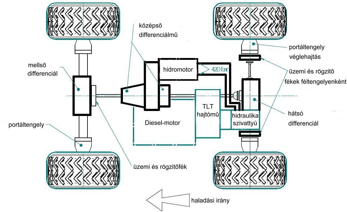
Figure 1.24 The drive system of TerraTrac (source: AEBI machine catalogue)
On Figures 1.25 and 1.26 the top category of the prime mover family is shown.
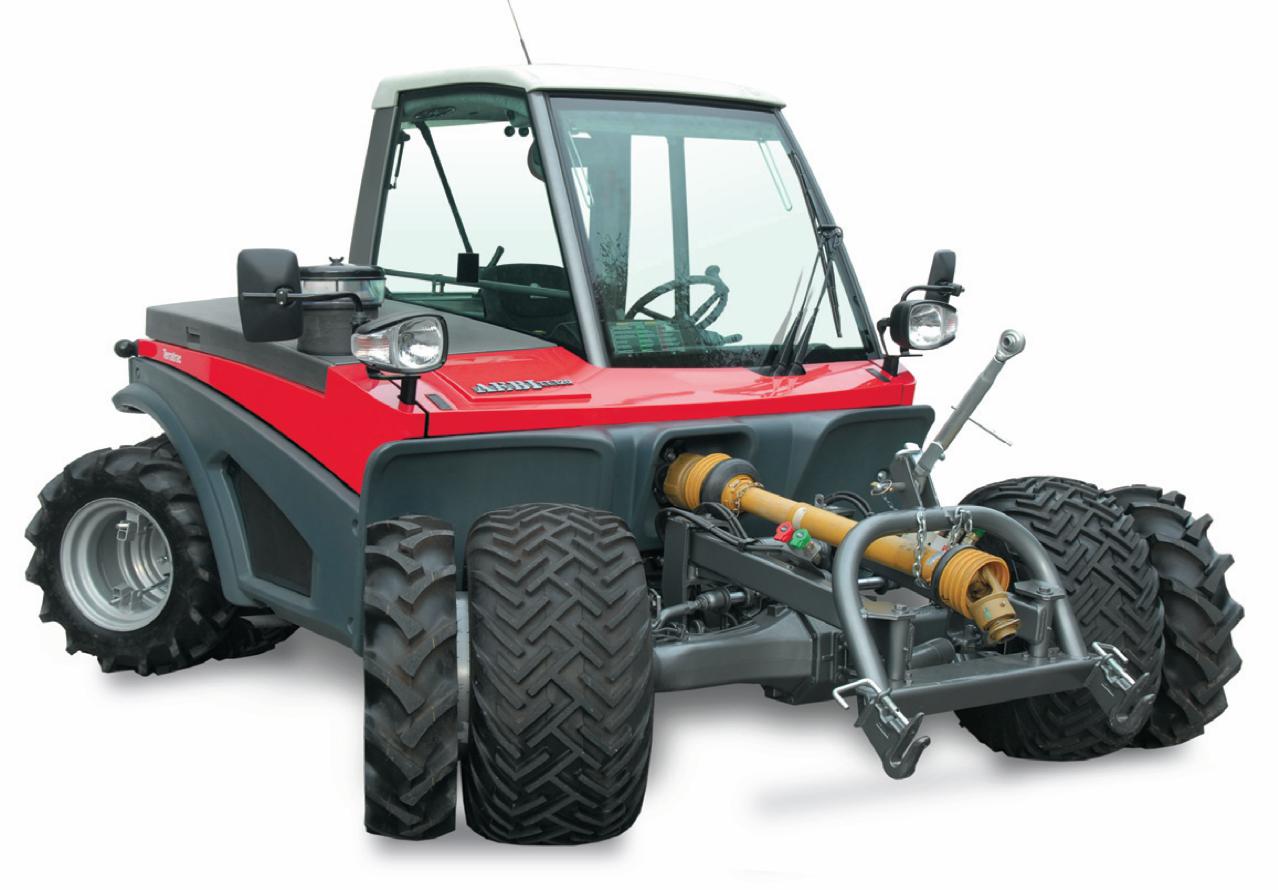
Figure 1.25 TerraTrac TT270
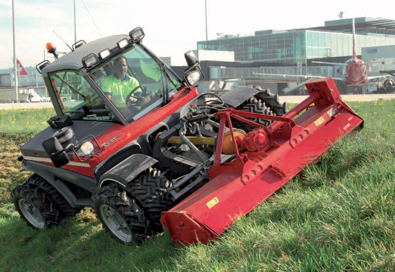
Figure 1.26 TT270 in use (equipped with a soil miller)
|
TerraTrac lawn mowers in use |
|
Extreme slopes
|
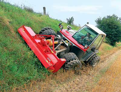
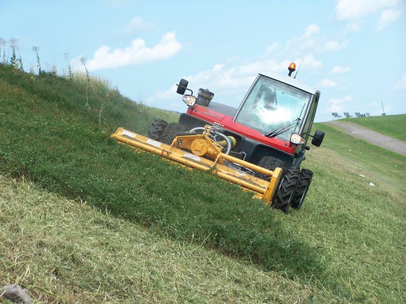
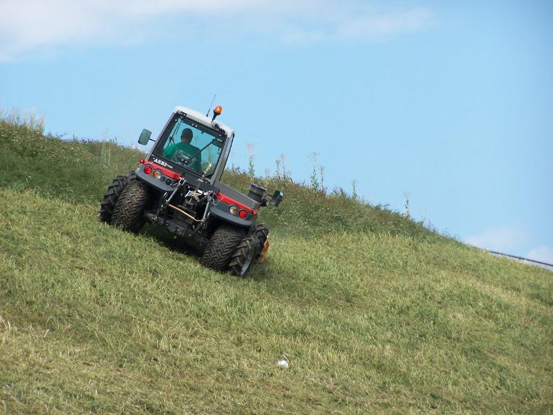
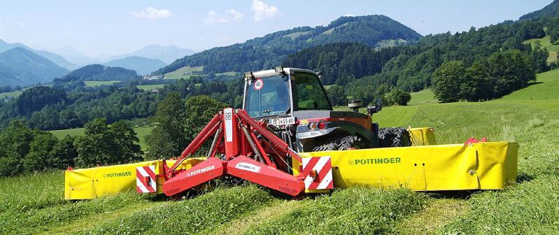
Figure 1.28 Applications of TerraTrac lawn mowers
The machines used as examples on Figure 1.28 illustrate this version’s suitability for work on steep slopes.
When using lawn mowing adapters, deteriorating work quality resulting from sudden changes in the field may be prevented by the front hitch intelligent field-profile tracking device (Figure 1.29) which functions with an electronically steered hydraulic pressure adjusting equipment.
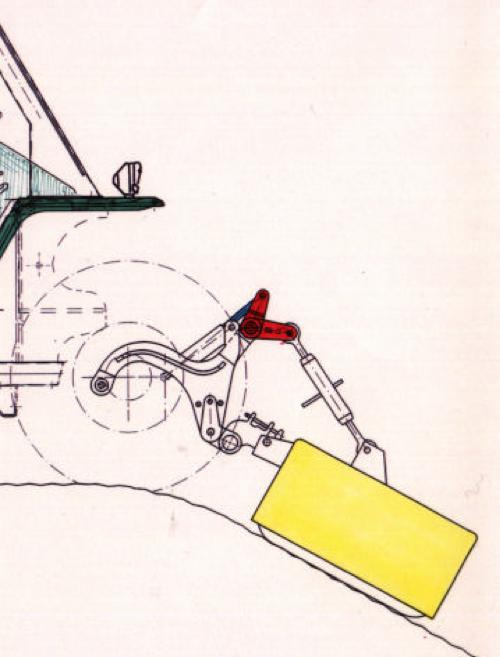
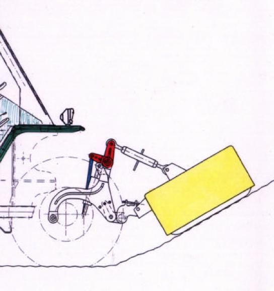
Figure 1.29 a) sudden slope, b) sudden climb
Although this version was originally developed for lawn mowing, its current design allows its universal application in difficult field conditions as well. As a result of different attachment possibilities, the availability of various adapters, and the good cross-country capability, it can be used for mulching, snow clearance, snow milling, but it is also capable of towing or transporting smaller machines.
Communal tractors
By developing the basic machine, AEBI created the KT (KommunalTrak) family with articulated steering and a rear loading area. Its different versions are primarily used in the cities for cleaning and in parks for lawn mowing and garbage collection (Figure 1.30).
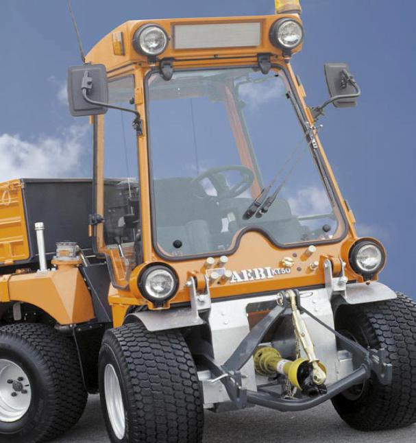
Figure 1.30 AEBI KT-50
As a result of the various possibilities for attaching adapters, the AEBI machine family marked with MFH (MachinenFabrik Hochdorf) is excellent for cleaning and watering city streets and roads, and foliage and snow clearance (Figure 1.31).
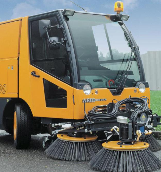
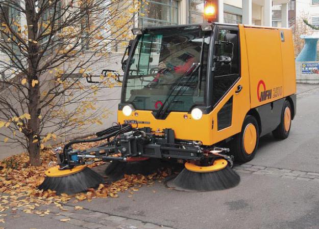
Figure 1.31 MFH2500 Street cleaning machine
The TP (TransPorter) transporter-vehicle family utilizes the cross-country feature of the basic machine. It is suitable also for use on steep slopes and has a 6x6 drive, pick-up transporter version (TP97) as well (Figure 1.32).
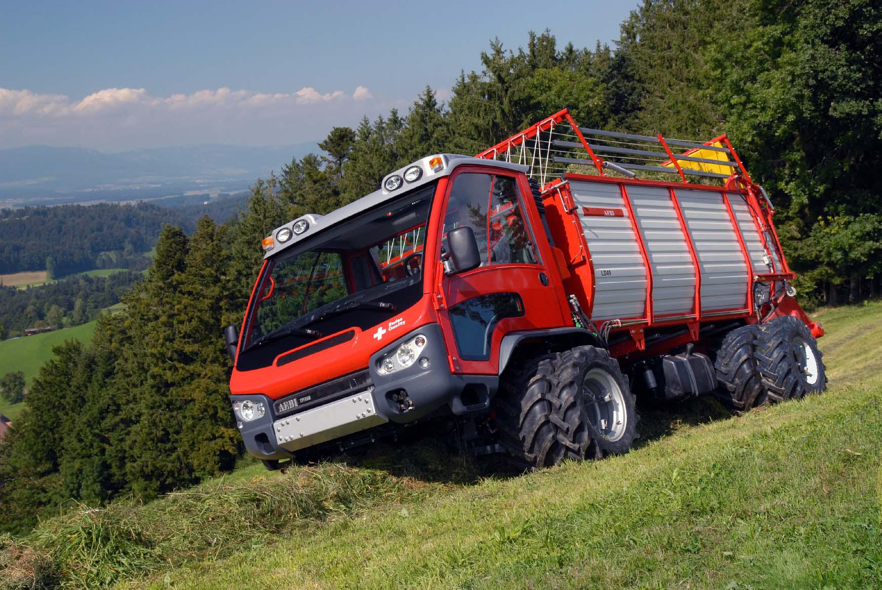
Figure 1.32 TP transporter
Small-sized horticultural tractors
There is a constantly increasing demand for small-sized machines of universal application with extremely good turning capability and a wide variety of adapters.
The Bobcat category used since the 1960s, is the best representative of this structural design.
AVANT Tecno
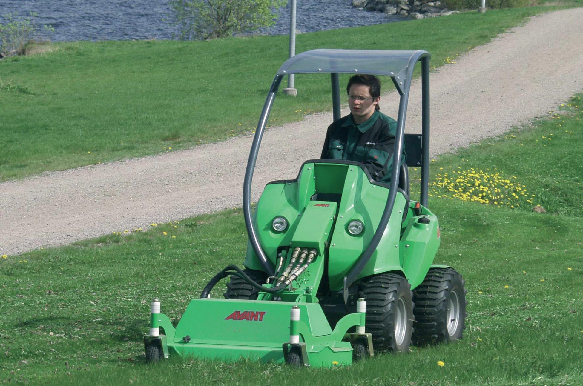
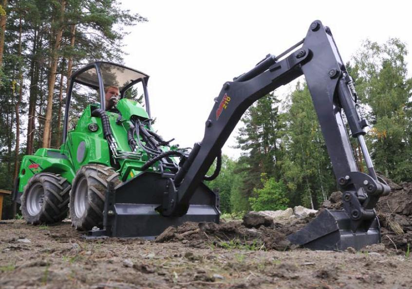
The latest machine family in this category is the machine variety of the Finnish company, AVANT, founded in 1991, which is best known for its front adapter attachment. The multi-faceted Avant small machines are suitable for performing tasks in a variety of narrow spaces (in the construction industry, agriculture, garden and park landscaping, maintenance) whether the task is soil work, loading or even lawn mowing (Figure 1.33).
The characteristics of this machine family are the following:
-
Constant, all-wheel (4x4) hydrostatic drive with hydro-motors built into the wheels. Steering is done by two pedals. One regulates the speed of forward travel, the other the speed of backward travel, with continuous or infinitely variable transmission. The speed is proportionate to the pressure on the pedal.
-
Wide variety of motors between 13-50 kW (18-70 HP) (petrol or diesel).
-
Skid-steering (possibility for the tractor to turn in its own length) or articulated steering to protect soil and grass.
-
Modern solution for front hydraulic adapter attachment (“boom”). The front lifting may be steered by joystick-style arms.
-
Level controlling arm: possibility for automatic switching to horizontal position.
-
Variety of adapters: universal application, multi-functionality (more than 50 types of adapters are available, for example, for soil work, loading, and different adapters driven hydraulically).
-
Rear towbar: towing possibility.
-
Low center of gravity ensures great stability.
-
Operator’s comfort: cab with 360°visibility, protective roof, tubular frame providing protection in case the tractor rolls over (Roll-Over Protection System).
-
Options: revolving light, etc.
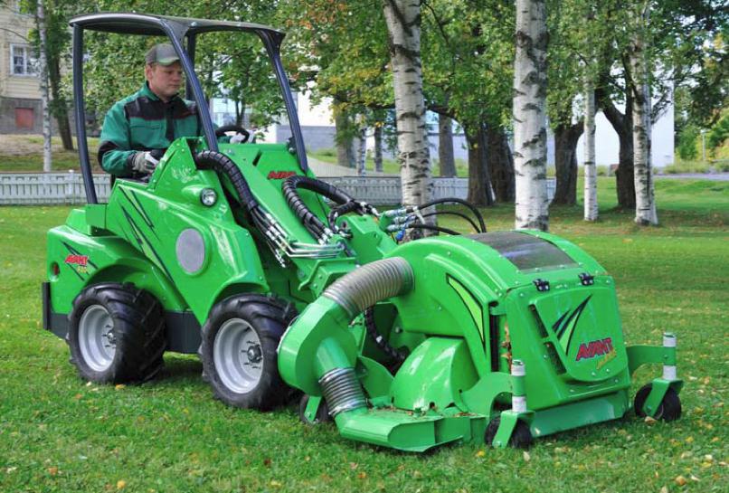
Figure 1.33 Avant Tecno lawn mower with adapter
The Avant machine family is similar to the Bobcat in some respects. One similarity is that some of its versions also use the skid-steer steering system applied by Bobcat in order to achieve a smaller turning circle and to enable the tractor even to turn in its length.
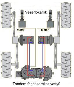
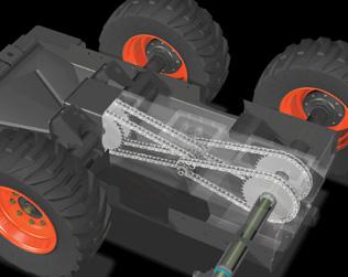
Figure 1.34 a), b) The theoretical construction of Skid-Steer
Skid-steer is the typical steering method of small-sized trucks and universal mini-loader machines requiring great flexibility. Skid-steer actually utilizes the principle of caterpillar steering and all its operational methods (including when the tractor turns in its length) on vehicles running on wheels.
The small diesel motor drives a dual cog-wheel pump which supplies high-pressure oil to a hydro-motor mounted on each side. The speed and the turning direction of the two hydro-motors may be adjusted with continuous or infinitely variable transmission by two joysticks. Each of the hydro-motors turns the wheels on its own side with forced-connection drive (usually with chain drive) in order to achieve complete synchronization. By appropriate steering simultaneously on both sides it can be achieved that the wheels on the two sides turn with the same speed but in the opposite direction. As a result of this, the machine’s turning center will be a point to be determined by the half of the axle distance and the half of the wheel track, meaning that the machine turns in its own length. The disadvantage of this method is that moving on hard (for example, asphalt or concrete) surface greatly wears out the tires because of their slipping, and moving on soil damages the soil substantially (Figure 1.34).
The real innovative feature is the front adapter attachment. This is located on a middle arm that may be lifted. The hydraulic attachments necessary for driving the active adapters are placed also on the middle arm (Figure 1.35).
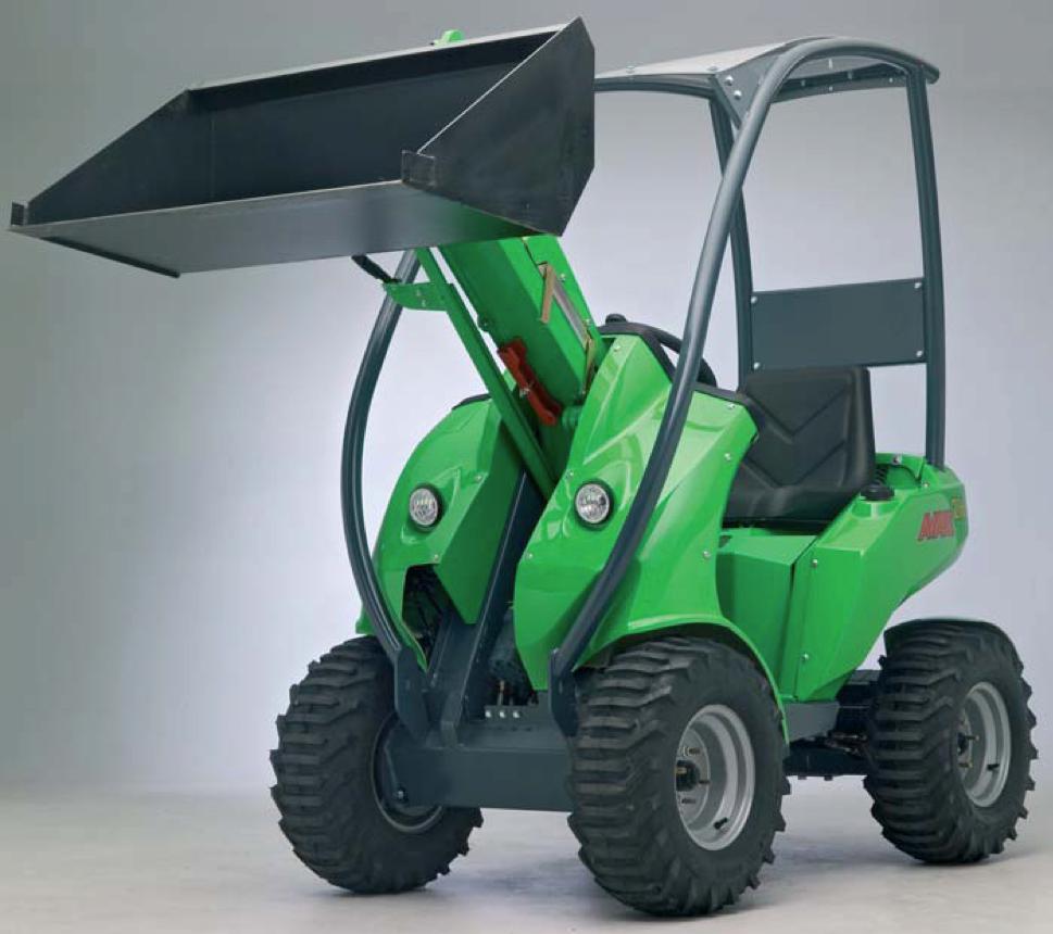
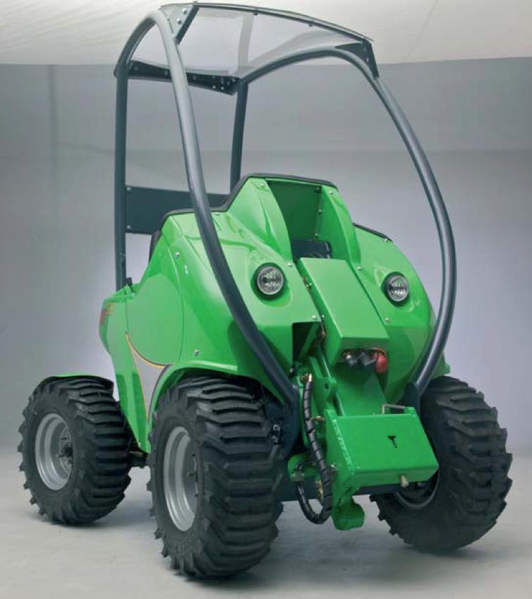
Figure1.35 Avant Tecno front hitch a) elevated b) lowered
Articulated steering (Figure 1.36) decreases damage to the soil and the plants. Figure 1.37 shows an example for the operation of the level controlling arm with the possibility for switching automatically to a horizontal position.
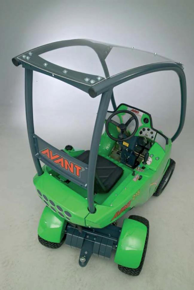
Figure 1.36 Articulated steering
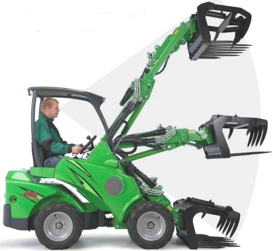
Figure 1.37 The automatic leveling of the elevating arm
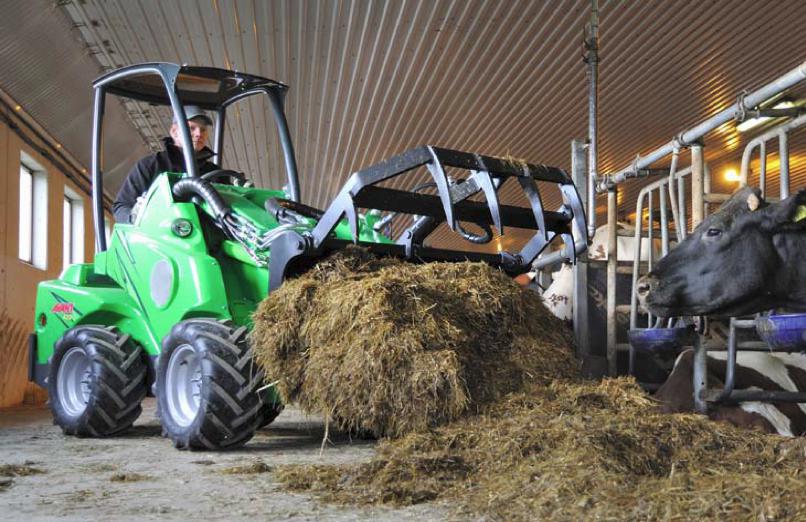
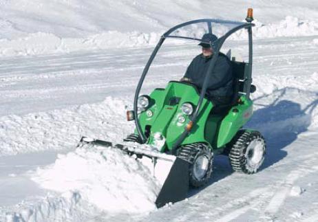
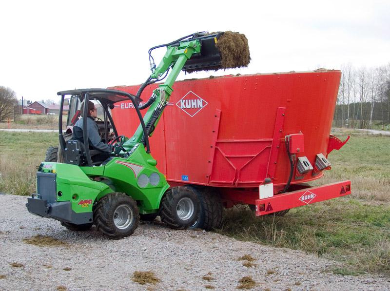
Figure 1.38 shows some characteristic applications of the small-sized machine.
-
Application possibilities of the AVANT Tecno series
Lawn mowing
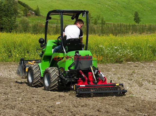
Earth work
Fodder treatment
Snow clearance
Towing
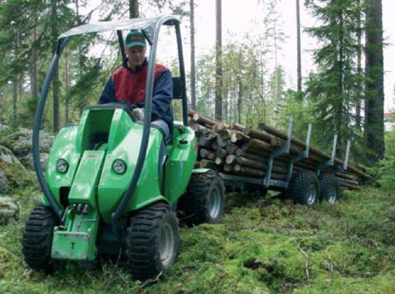
Loading
Bale grapping adapter
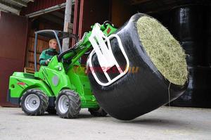
Figure 1.38 Avant Tecno applications
Application of Quad (ATV) in horticulture
This machine was developed in the 1960s in Japan for the purpose of enabling travel from closed-off mountain villages to towns. Not surprising, therefore, that even today the most well-known manufacturers of these machines are Japanese companies, such as Honda, Yamaha and Kawasaki.
By 1970, the Qaud appeared also in the US, first as a sports vehicle. Since 1980, American farmers have started to use it in field traffic, transportation and, later on, in forestry, horticulture, and grape cultivation as well, even in animal breeding, for example, in cattle driving.
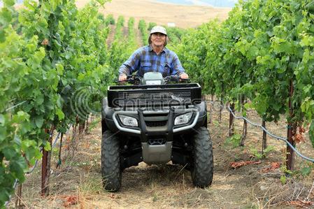
Today, the “quad” vehicle is often used in horticulture because of its small size, flexibility, good cross-country capability. If used as commercial vehicles they are usually called ATV (All-Terrain-Vehicle). Currently, there are many different adapters and fittings available. For example, towbar, front or rear hitch systems, or even PTO can be ordered (Figues 1.39, 1.40 and 1.41). In the US, the law defines it as a separate category (MAV: Multipurpose Agricultural Vehicle)..
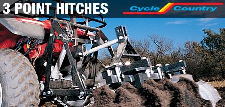
Figure 1.39 3-point hitch on an ATV
The main features of ATVs are the following:
-
All-wheel drive.
-
Its motor is usually bigger than 400cm3.
-
Its capacity is greater than 25 kW (35 HP).
-
Its mass usually exceeds 350kg.
-
For transporting smaller masses, it usually has a front and rear loading area.
-
It is supplied with towbar.
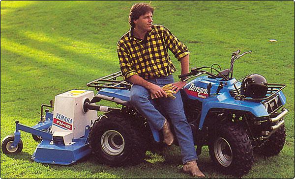
Figure 1.40 Yamaha ATV manufactured in 1988, supplied with a transmission shaft (Terrapro PTO)
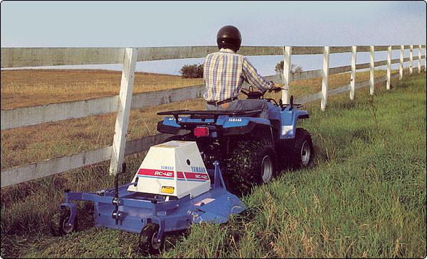
Figure 1.41 Lawn mowing with an ATV supplied with a transmission shaft
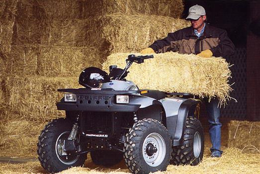
The quad as an ATV has become a useful, multi-functional machine on farms.
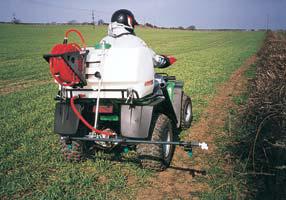
On Figure 1.42 several agricultural applications can be seen.
|
Agricultural/horticultural application of the ATV |
|
 |
Transportation
|
 |
 |
|
Spraying
|
Lawn mowing
|
|
Towing
|
|
|
Field leveling
|
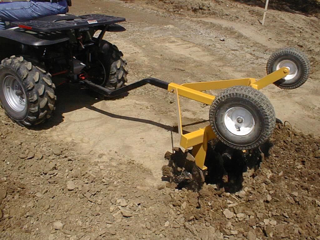 |
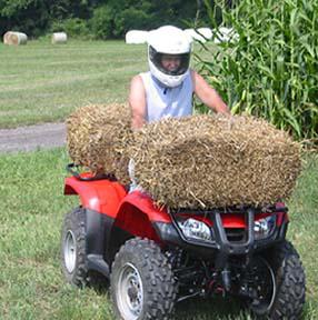
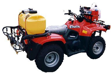
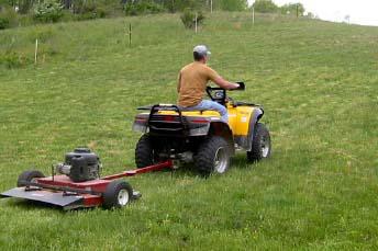
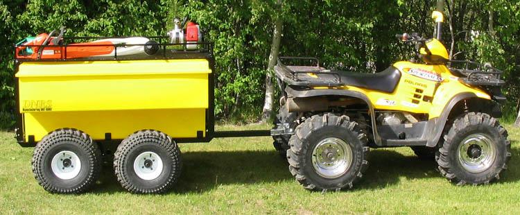
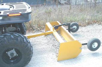
Figure 1.42 Agricultural applications of the ATV
Control questions:
1/ How can the agricultural tractors be classified?
2/ Which are the main characteristics of a plantation tractor?
3/ How does the SuperSteer steering is working? Sketch its arrangement!
4/ Sketch the construction of the zero-turn lawn tractors!
5/ Why is the stability of the loan tractors important? How can their stability ensured?
6/ Characterise the modern universal small tractors!
7/ How does the skid-steering works?
8/ What does the ATV is meaning? In which area of the agriculture can they be used?
![]()
![]()

Hírek/News
Sajtóközlemény
A projekt célja magyar és angol nyelvű digitális tananyagok fejlesztése a Budapesti Corvinus Egyetem Kertészettudományi Karának hét tanszékén. Az összesen 14 tananyag (hét magyar, hét angol) a kertészmérnök Msc szak és a multiple degree képzés keretében kerül felhasználásra. A digitális tartalmak az Egyetem e-learning keretrendszerével kompatibilis formában készülnek el.
BővebbenSikeres pályázat
A projekt célja magyar és angol nyelvű digitális tananyagok fejlesztése a Budapesti Corvinus Egyetem Kertészettudományi Karának hét tanszékén. Az összesen 14 tananyag (hét magyar, hét angol) a kertészmérnök Msc szak és a multiple degree képzés keretében kerül felhasználásra. A digitális tartalmak az Egyetem e-learning keretrendszerével kompatibilis formában készülnek el.
A tananyagok az Új Széchenyi Terv Társadalmi Megújulás Operatív Program támogatásával készülnek.
TÁMOP-4.1.2.A/1-11/1-2011-0028
Félidő
A pályázat felidejére elkészültek a lektorált tananyagok, amelyek feltöltése folyamatban van.
![]() TÁMOP-4.1.2.A/1-11/1-2011-0028
TÁMOP-4.1.2.A/1-11/1-2011-0028