Trellises in fruit and vegetable production
3. Trellises in fruit and vegetable production
Trellises have been used recently on most fruit plantations and more and more in field vegetable production, because they enable advantageous limb structure of branches (optimal assimilation) in one (or more) plane(s), prevent damage due to strong wind, make chemical plant protection and handling of plants easier (pruning, thinning, etc), facilitate the mechanisation of harvesting, and the automation of irrigation and fertilisation.
Planning the main parameters of the plantation
Before designing and dimensioning a new trellis, one must decide on the variety of draft or semi-draft trees or vegetables to be planted. The tree or bush height and the weight of the yield greatly influence the design. Higher trees/bushes need more distance between the rows to get enough light.
Sunlight and wind direction play an important role in determining the location of the rows on the available area. The location of the rows should also allow the unlimited movement of workers and machines. The distance between the row ends and the plantation boundary should enable the unlimited turning of machines and equipment. The size and shape of mature trees/bushes should be taken into account, allowing enough space for manual tasks like thinning, pruning and harvesting.
The main elements of trellises are the
-
line posts,
-
end posts,
-
anchoring elements,
-
wires,
-
wire strainers, and
-
staples for wooden posts.
Posts can be made of steel reinforced concrete, wood, steel, fibreglass or plastic.
The classification of trellises can be made as follows:
- individual: one support for each plant
- I shape : plants on one vertical plane
-
Y, V, T, F shape: plants on more planes
3.1 Designing and dimensioning of trellises
Designing and dimensioning of trellises means determining the optimal material, size and arrangement of their elements by taking into account the load acting on them.
The calculation below will be carried out by using the example of an apple orchard with the following data (Figure 3.1):
-
Yield : Q=50 t/ha, with the assumption that only half of its load is on the wires
-
Length of the posts above ground: h = 2 m
-
Diameter of the post: D = 9 cm
-
Diameter of the wire: d
(to be calculated)
-
Distance between the posts: l = 4 m
-
Distance between the rows: b = 1.8 m
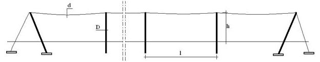
Figure 3.1 The main elements of a simple trellis
The load on the trellises are the weight (mass) of the plantation (limb and yield) and
the horizontal load resulting from the wind.
The limb load per meter on the trellis can be calculated as follows:
p p = 0.5 . Q . g . b/1,000=25,000 (kg/ha) . 9.81(m/s 2) .1.8 (m ) / 10,000 (m 2/ha)= 44 N/m (1)
The specific surface value of wind load, according to DIN may be chosen for pwst=50 N/m2. Assuming that the foliage of the limb covers only 50% of the total vertical surface, the force acting on the surface h x l is:
F w = p w st . h . l . 0.5= 200 N (2)
This force may be divided between the top and the bottom of the hedge (Figure 3.2). The specific linear force acting on the wire at the top of the pole, due to the wind is then
p w = F w / 2/l=100/4=25 N/m (3)
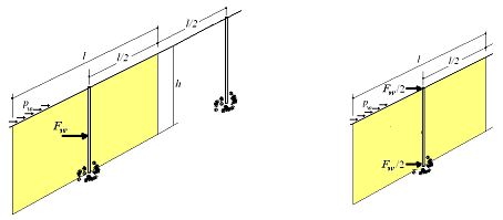
Figure 3.2 Concentrated force replacing wind load
Load on the posts
The vertical posts are pressed by the limb vertically and bended by the wind horizontally.
3.1.1 Basic calculations to design and control the elements of trellises
3.1.1.1 Tensile and compressive stress
Stress is the way in which a force F is spread over per unit area A of a cross-section (Figure 3.3). When the concentrated force F is equally distributed over a drawn/compressed cross section, it is called normal stress: σ = F/A (N/ mm2)
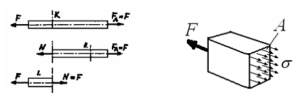
Figure 3.3 Explanation of the stress σ
3.1.1.2 Stress upon bending
If we cut a bended beam in parallel layers, there is always one, the length of which does not change. It is called the neutral layer. On one of its sides the layers become longer, on the other they get shorter (Figure 3.4).
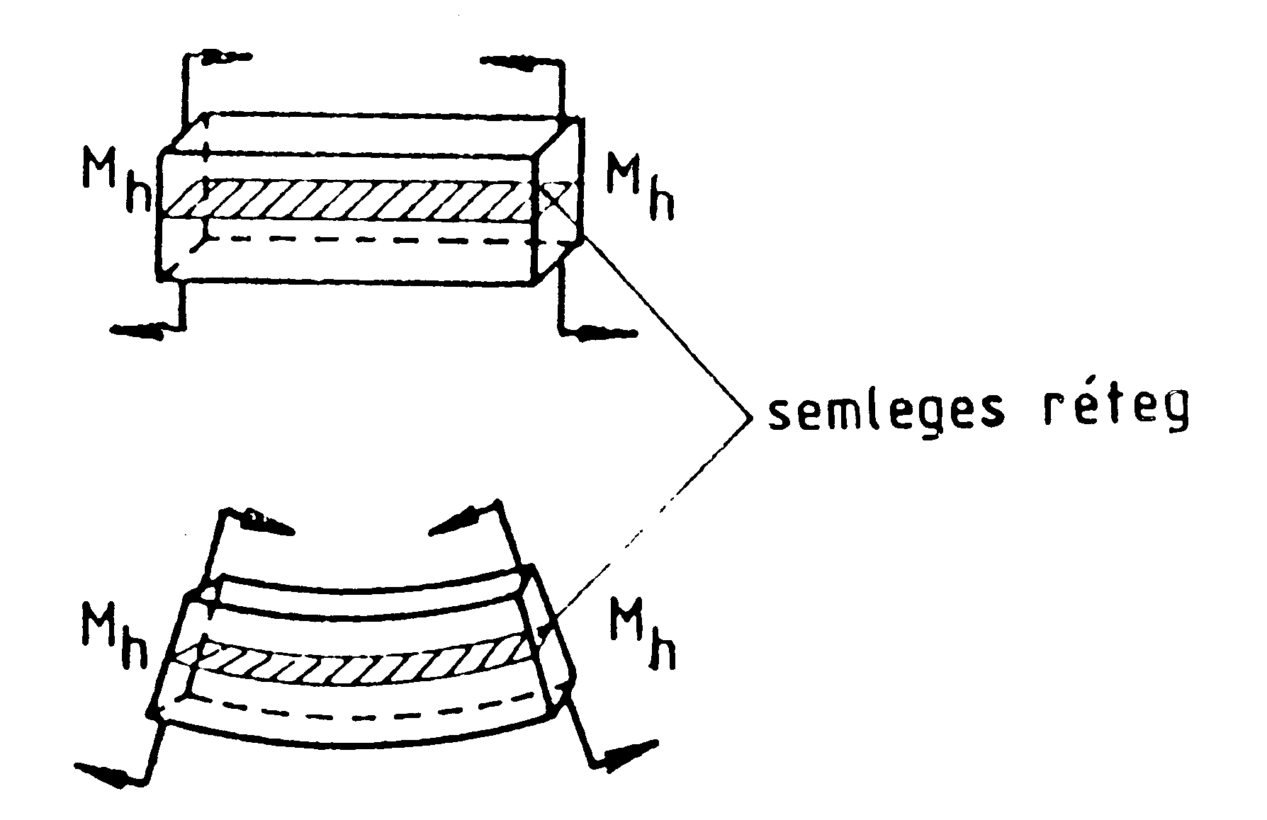
Figure 3.4 The neutral layer upon bending
We may say that, upon bending, normal tensile and compressing stresses are present (Figure 3.5), however, they are not uniformly distributed. Assuming that the change of σ is linear we get the stress distribution shown on Figure 3.5.
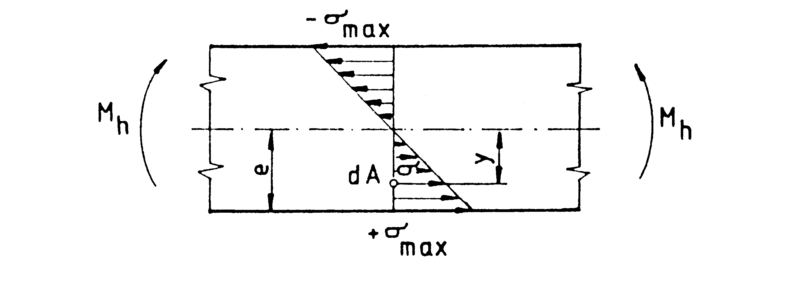
Figure 3.5 Distribution of normal stress upon bending
The bended beam is in equilibrium when the acting (Mh) and the reacting (Mb) bending moments are equal: Mh = Mb
The reacting bending moment is the sum of the moments of internal forces dF for the whole cross section A, regarding the neutral layer.. For area dA, the force is: dF= σ . dA
With this, the bending moment for area dA (Figure 3.6):
d M h = σ .dA.y= dF.y (4)
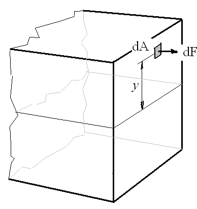
Figure 3.6 The elementary moment of bending
The reacting moment for the whole cross section:
M h = ∫ σ .dA.y= Mb (5)
According to Figure 3.5, one can arrive at the following ratio: σ/ σmax=y/e
or σ= σmax.y/e. (6)
Based on this, Mh =∫ σmax. y. 1/e .dA.y= Mb (7)
finally: Mh = σmax.1/e ∫. y2.dA, (8)
The integral ∫. y2.dA is called the moment of inertia: I=∫ . y2.dA (m4)
The moment of bending expressed with the moment of inertia:
M h = σ max . I/e (9)
Fraction I/e is the factor of cross section (K): K = I/e (m3) (10)
With this, the maximum tensile/compressing stress upon bending is:
σ max = M h /K [Pa] (11)
3.1.2 Dimensioning of the wire
The tensile force H in the wire, according to the often used equation for chains, fixed on both ends:
H= p . l 2 /( 8 . f) (12)
where p is the sum of the limb and wind load N/m
f is the billow
l is the distance between the poles (Figure 3.7)
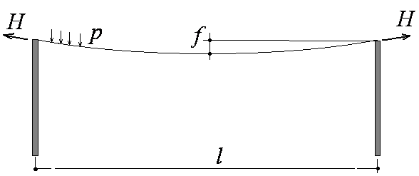
Figure 3.7 The components of calculating force H
The sum of limb and wind load/m can be calculated as follows:
p=( p p 2 + p w 2 ) 0.5 (13)
With the above data: p=( 44 2+ 25 2) 0.5=51 N/m
Let us choose for the billow for f = 3 cm (data taken from practice). The tensile force in the wire is then: H = 3400 N
Calculation of the appropriate wire diameter
The tensile strength of the wire materials (according to the standard for steels): Rm =550-900 N/mm2. To remain on the safe side, we calculate with the lower value.
The load on the trellises may be regarded as dynamic so the coefficient of safety should be chosen for z = 1.5
Then the allowed stress in the wire σall =Rm/z=367mm2
The required wire cross section: Areq=H/ σall =d 2.π / 4 (14)
Based on this, the required wire diameter: dreq={4.H /(σ all .π}0.5 (15)
With the above data: dreq={4.3400 /(367 .π}0.5 =3.44 mm
The nearest wire diameters in the standard are 3.0, 3.5, and 4 mm.
To be on the safe side, we chose: dreq= 3.5 mm
In case of two parallel wires on the trellis (one on the top and one in the middle), and assuming that
p p 2 = p p / 2 as well as pw2 = pw /2 ,
the new tensile force in the wires will be H2 = 1,700 N, and the required diameter for the two wires will be then:
d req ={4 . H 2 / ( σ all . π } 0.5 = 2.5 mm
3.1.3 Controlling the line posts
The line posts are pressed by the limb vertically and bended by the wind horizontally.
3.1.3.1 Control for compression
The vertical force (G) acting on the post = the vertical load of the limb before and after the post on the length l/2 (Figure 3.8):
G= 2.0.5 l . pp = l . pp =4 . 44 =176 N (16)
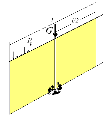
Figure 3.8 Vertical force (G) acting on the post
The compressing stress is: σpg = G/A=4 . G/ (D 2. π ) (17)
In case of an acacia post with a diameter of 9 cm: σpg =2.77 N/cm2, which is much less than the allowed value of 6,500 N/cm2 set forth in Table 3.1 below.
Table 3.1 Main strength properties of acacia wood
-
σ pgall
6,500 N/cm2
σ bendcrit
1,350 N/cm2
E
1.8 .106 N/cm2
3.1.3.2 Control for buckling
Buckling may damage long and thin rods. According to Euler, force Fk resulting in breakage is:
F k = π 2 . I min . E / s k 2 (18)
where
s k is the length of a rod as shown on Figure 3.9
I min is the minimum moment of inertia
E is the modulus of elasticity.
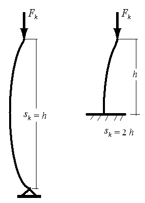
Figure 3.9 The length of a rod of trellis posts
In our case sk = 2 .h
The minimum moment of inertia for a cylindrical post: Imin= I = D4 . π / 64 m4 (19)
Its calculated value: Imin =322 cm4 . With E taken from Table 3.1 (E=1.8 .10 6 N/cm2), the critical force of buckling is
F k =35753 N.
As G, the vertical force, acting on the post is much less than Fk , no buckling is to be expected.
3.1.3.3 Control for bending
Wind may bend the posts. The force acting horizontally on the post in the centre of the area l . h is 200 N. The moment of bending due to Fw on each post is then (Figure 3.10):
M bend = Fw .h /2= 200 N (20)
The maximum bending stress in the post: σbend = Mbend / K0
where K is the factor of the post’s cross section (see above):
K = I / e = D3 . π / 32= 71.6 cm3 and e=D/2
With the data above: σbend = 279 N/ cm2 which is less than the critical bending stress value of the acacia wood (see Table 3.1: σbendcrit =1,350 N/cm2).
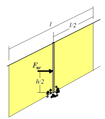
Figure 3.10 Bending moment on the post, due to wind
3.1.4 Control of the post in the sole
3.1.4.1. Control of the soil resistance in vertical direction
The post must not slip vertically into the soil. To check this, let us compare the acting and the reacting forces.
The acting force is G (the vertical force on the post). The reaction must come from the soil:
F soil = σ soil . A (21)
where
σ soil is the normal stress in the soil
A is the cross section of the post
The normal stress in the soil underneath the post is the same as that inside the post in the vertical direction:
σ pg =G/A=4 . G/ (D2. π ) (22)
The average specific soil resistance: σsoilspec = 10 N/cm2, taken from engineering practice.
As σpg =G/A=2.77 N/cm2 is less than the specific soil resistance, the post will not slip into the soil.
3.1.4.2. Control of the soil resistance in horizontal direction
The question arises as to how deep the post should be sunk into the sole to resist the horizontal load of the wind.
Let us presume that the depth of the post in the sole is x and its virtual turning centre is
in a depth of x/2.
If the acting and the reacting forces and moments are in balance, the soil must react to the moment Fw (h/2+ x/2) and the horizontal force Fw (see Figure 3.11).
On Figure 3.11, σ1 represents the maximum soil stress on the post’s surface when the post turns. The volume of the triangles gives the values of the concentrated forces E which are located in the centre of gravity (presuming that the soil stress along the post is linearly distributed).
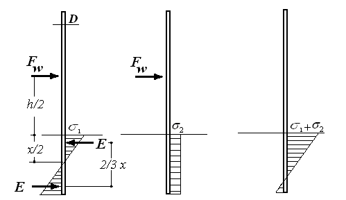
Figure 3.11 Active and reactive forces acting on the post in the soil
Forces E can be calculated as follows (Figure 3.12):
E =x/2. σ1/2. D= (x. σ 1)/4. D (23)
Now the equilibrium of the moments:
F w . (h+x)/2= x/2.σ1/2. 2x/3 . D= σ1. x2.D/6 (24)
(Note that the arm of the reacting moment is 2x/3)
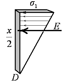
Figure 3.12 Replacing the soil pressure with concentrated force E
A second equation can be set up for the equilibrium of the horizontal forces:
F w = σ2 .x .D (25)
where σ2 is the soil stress due to force Fw (see in the middle of Figure 3.11).
When the post stands stable in the soil, the sum of soil stresses must not surpass the specific soil resistance. This gives the third equation of equilibrium:
σ 1 + σ2 ≤ σsoilspec (26)
Solving now the three equations, we get the following expression for x:
x = {Fw +(Fw2+7.5.D. F w.h)0.5}/(5.D) (27)
Replacing D and h (both in cm): x = 41 cm
Taking into account that the surface layer of the soil is cultivated, the reason for its being loose, the posts should be sunk 60-70 cm deep into the soil.
3.1.5. Control of the end posts
Force H =3,400 N loads horizontally the two end posts of the row. If they stand vertically, the reacting forces are N 1 and S1, as shown on the left side of Figure 3.13.
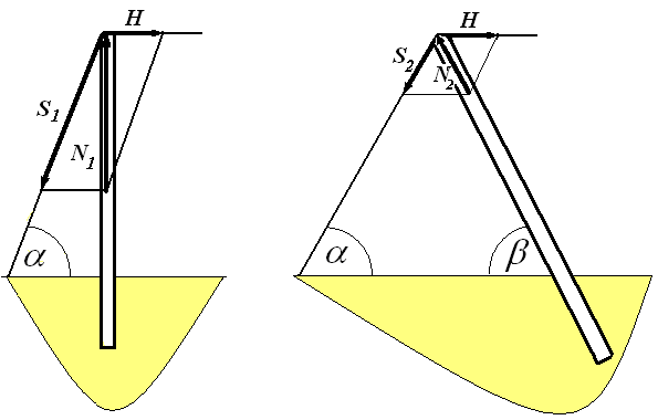
Figure 3.13 Vertical and tilted end posts
When tilting the post by β, the reacting forces change (see the right side of Figure 3.13), but in this case a longer post is needed. In general, the two reacting forces are:
N = H /{sinβ. (ctg α+ctg β)} and (28)
S=N . sin β /sin α (29)
The value of angles α and β are optional. If both are 600, all three forces are equal: N2 = S2 = H
Let us review the following arrangements:
-
Vertical end-post without anchoring
2. Vertical end-post with α = 600
3. Tilted end-post, α = β = 600
-
Vertical end-post without anchoring
The post must be sunk deep enough to get the necessary reaction force due to H. Using the earlier equation for x:
x = {H +(H2+15.D. H .h)0.5}/(5 .D)=154 cm, which is irrationally deep.
2. Vertical end-post with α = 600
The two equations above can be used for the calculation of the reacting forces for N and S, with the presumption β =0:
N 1 = H /ctg α=5,889 N and S1 = 6,800 N
It is now necessary to perform the following control calculations for the end post:
-
Control for the post’s compression: σpg =92.6 N/cm2, less than 6,500 N/cm 2, no damage
-
Control for buckling: Fk =35,753 N > N1, no risk of braking
-
Control for slipping into the soil: N1/A=92.6> σsoilspec the post slips into the soil. By increasing contact area (A), the problem can be solved.
The increased area (e.g. a concrete plate) must be: A ≥ N1/σsoilspec=589 cm2
3. Tilted end-post with α = β = 600
In this case N2 = S2 = H= 3,400 N
The new post length: h’=h/cos300= 2.3 m
The buckling force for this longer post is F’k =27,034 N, more than the critical tensile force N1 . No buckling is to be expected.
Control for the post slipping into the soil: N2/A=53,4> σsoilspec , the post slips into the soil in this case as well.
By increasing contact area (A), this problem can be solved here as well. The increased contact area must be:
A ≥ N2/σsoilspec=340 cm2
Increasing the contact area under the end post can be done by applying
- a support plate (see on the left side of Figure 3.14) or
- concrete reinforcements (see on the right side of Figure 3.14).
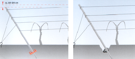
Figure 3.14 Increasing the contact area under the end post by a support plate and by concrete reinforcements
3.1.6 Designing the anchoring of wire in the soil
Force S at the end post must be balanced. For this purpose anchors are sunk into the soil. The most often used anchor elements are concrete plates and metal helix plates (Figure 3.15).
The dimensioning of anchors means the determination of the anchor’s depth in the soil and/or its surface.
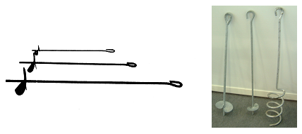
Figure 3.15 Metal helix plates as anchoring elements
The anchoring element will resist force S as long as the stress in the soil along the sheered area is less than the critical sheer stress of the soil (Figure 3.16):
τ s ≤ τ =S/(U . x h ) (30)
Where
τ s is the critical shear stress of the soil
U is the circumference of the anchoring element
x h is the depth of the element in the soil.
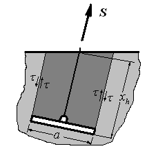
Figure 3.16 The anchoring element in the soil
From those: xh= S/(U. τs) (31)
Replacing S1 and S2, and with the helix plate diameter D=12 cm, the circumference is U=D.π =37.7 cm, τs = 3 N/cm2 is the critical sheer stress of the soil, taken from engineering practice.
The results with the above equation are the following:
- at vertical end-post (S1 = 6,800 N) : xh1 = 60 cm,
- at tilted end-post (S2 = 3,400 N) : xh2 = 30 cm.
The data above is valid for well-compressed soil. In case of a cultivated surface, these values
should be increased by 20-30 cm.
Control of the wire diameter between (end-post and anchoring element
Acting force S may be greater than H. In this case, the diameter of the wire should be recalculated, as shown earlier.
3.1.7 Results and conclusions of the calculations
Let us compare our calculated values with some recommended trellis parameters published in a journal for growers (Figure 3.17).
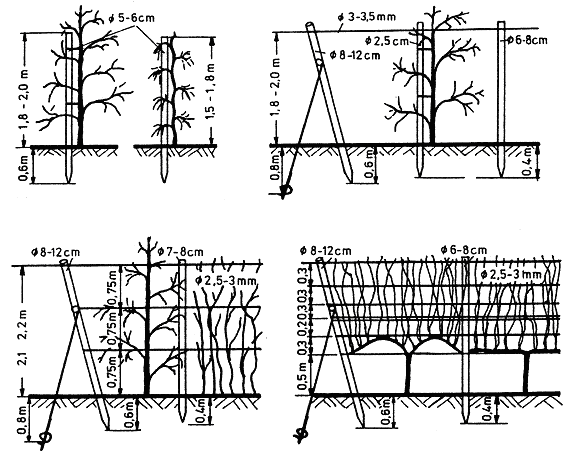
Figure 3.17 Recommended trellis parameters published in a journal for growers
-
The calculated diameter of wires IS SIMILAR TO THOSE published in the journal, both in case of single and multiple wiring.
-
The diameter of posts controlled in the above calculations does not deviate from the diameter published in the journal.
-
The calculated depth of posts in the soil is 41 cm, the same as the recommended figure.
-
For the end posts the paper does not recommend any bolster plates. Instead, the depth in the soil is increased.
Based on the foregoing, we can conclude that the above calculations are of practical use and enable the design even of new trellis forms.
3.2 Building trellises
After having determined the main parameters of the plantation, the building of trellises means the following activities:
-
Setting the line and the end posts,
-
Setting the anchoring elements
-
Laying, fastening and straining the wires
Before building the trellises, the soil of the plantation must be checked as it can greatly influence the type of materials and the method of construction.
3.2.1 Post driving methods
Posts can be set both by digging and manual tamping or driving.
3.2.1 Post driving by digging
For digging holes a large variety of tools and machines are available, starting from hand-held drills to tractor-mounted drilling machines (Figure 3.18).
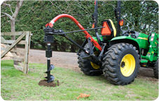
Figure 3.18 Tractor-mounted drilling machine
3.2.1.2 Static post drivers
Post drivers can work statically and dynamically.
Static post drivers are tractor-mounted tools; their main working elements are hydraulic cylinders.
Figure 3.19 shows a static post driver mounted on the side of the tractor. In hard soil, first a provisional hole is drilled (washed out) hydraulically using water from the tank carried by the tractor. Second, the post is pressed into the hole by the pushing plate of the machine.
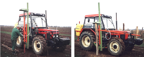
.Figure 3.19 Static post drivers with hydraulic driller
Static post drivers are fast, simple, and cheap tools although their driving capacity is limited by the weight of the tractor (if the soil resistance is too high, instead of driving the post, the tractor lifts itself up).
3.2.1.3 Dynamic post drivers
The other method of setting the posts, regardless of the soil type (soft, medium or hard, sandy or clay), is by driving them dynamically. Dynamic post-driving means hitting the top end of the post periodically by lifting and realising a heavy mass.
The simplest dynamic post-drivers are hand-held tools, with a weight of 6-8 kg, used for posts up to 65mm in diameter. It is actually an iron tube with one dead end and two handles (Figure 3.20). After fitting the tool on the end of the post, then lifting and pushing it down periodically, the post will sink gradually into the soil.
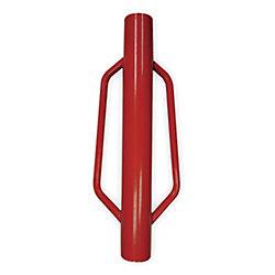
Figure 3.20 One-man operated dynamic post driver
Manpower can be saved if the lifting is done by high-pressure air. In this case, the hand-held tools are much heavier and are complemented by a compressor unit with a long air pipe.
In case of posts with larger diameter and where greater work-capacity is needed, tractor-mounted, hydraulically driven drivers are used. The mass of their “hammer” can reach 135 kg. In hard soil, post-setting may start by drilling a provisional hole using a powered auger. Some machines are supplied with both an auger and a driver unit.
Wood posts driven dynamically have greater resistance to being pulled out, pushed down and turned over than those set by digging and hand tamping.
3.2.2 Setting the anchoring elements
The most widely used earth anchors are made of high quality steel with a centre eye and a helix plate. For the purpose of protection, in most cases they are galvanized.
They are available for both manual and machine installation.
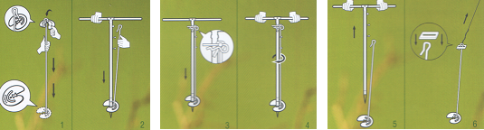
An example for manual installation is shown on Figure 3.21. The anchoring set consists of a helix plate, a wire with hooks on both ends, and a T shaped hand driver unit. The helix plate is connected to the bottom and the hand driver to the top end of the wire (1 and 2 on Figure 3.21.). The bottom end of the hand driver sits in the rectangular opening of the helix.
 v
v
Figures 3.21 A possible technique for driving the pulley by hand into the soil.
After fixing the wire to the hand driver, the procedure can start (3 and 4 on Figure 3.21). Upon reaching the necessary depth, the hand driver is disconnected from the wire and is pulled out of the soil. The upper hook of the wire is now ready for connection to the end post wire (5 and 6 on Figure 3.21).
3.2.3 Laying, fastening, and straining the wires
Laying the wire along the posts before fastening it is usually hard manual labour.
There are special trailers which carry the wire spirals along the plantation row. Figure 3.22 shows such a trailer capable of carrying 6 wire coils at the same time. A hydraulic lift helps loading and unloading. The wires are led among 3 rollers to prevent the spirals from rolling down freely.
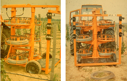
Figure 3.22 Trailer wire spirals along the plantation row
The wires are fixed onto wooden posts with staples. It is recommended to use a strainer for each wire to reach uniform stress. Simple strainers are shown on Figure 3.23.
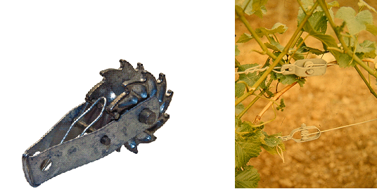
Figure 3.23 Simple wire strainers for building trellises
![]()
![]()

Hírek/News
Sajtóközlemény
A projekt célja magyar és angol nyelvű digitális tananyagok fejlesztése a Budapesti Corvinus Egyetem Kertészettudományi Karának hét tanszékén. Az összesen 14 tananyag (hét magyar, hét angol) a kertészmérnök Msc szak és a multiple degree képzés keretében kerül felhasználásra. A digitális tartalmak az Egyetem e-learning keretrendszerével kompatibilis formában készülnek el.
BővebbenSikeres pályázat
A projekt célja magyar és angol nyelvű digitális tananyagok fejlesztése a Budapesti Corvinus Egyetem Kertészettudományi Karának hét tanszékén. Az összesen 14 tananyag (hét magyar, hét angol) a kertészmérnök Msc szak és a multiple degree képzés keretében kerül felhasználásra. A digitális tartalmak az Egyetem e-learning keretrendszerével kompatibilis formában készülnek el.
A tananyagok az Új Széchenyi Terv Társadalmi Megújulás Operatív Program támogatásával készülnek.
TÁMOP-4.1.2.A/1-11/1-2011-0028
Félidő
A pályázat felidejére elkészültek a lektorált tananyagok, amelyek feltöltése folyamatban van.
![]() TÁMOP-4.1.2.A/1-11/1-2011-0028
TÁMOP-4.1.2.A/1-11/1-2011-0028