Machines used before and during planting. Soil cultivation in the production of vegetables, fruit and grapes.
Machines used preceding the planting
The meaning of the term „land improvement”, its main tasks and the preparation of the area for cultivation
The planting of horticultural plants (such as grapes, fruit, berry fruits, nurseries) requiring constant soil supply is preceded by careful planning and organization. The arable land must be capable of production, and all producers are obligated to maintain and protect its fertility.
The term „land improvement” means any effect (intervention, procedure, method) or system of effects on the soil, the purpose of which is to:
a) increase soil fertility permanently, and
b) terminate or substantially decrease unfavorable natural conditions.
Land improvement activity means performing all agro-technical, biological, chemical, and technological (soil protection, land drainage, water utilization and other) procedures in order to protect the fertility and the condition of the soil.
The elements of land improvement are the following:
-
re-shaping sloping areas,
-
soil protection (forest/shelter belts, erosion, protection against deflation),
-
water management (termination of water rills), drainage, and
-
soil improvement (changing the soil’s chemical reaction, for example, by using lime).
The purpose of land improvement is to perform any and all tasks on agricultural land in the interest of production, and to create the optimal conditions required for the application of production technology, work organization, modern technology, and effective soil protection.
LAND USE PLANNING
Before the geodesic marking of the land designated for planting, it may be necessary to remove trees, shrubbery, bushes, and stones preventing earth work. Two main categories of machinery are used in this phase, machines used in the field clearing and field shaping.
Machines in field clearing
-
machines used in clearing shrubbery and bush
-
bush crushers,
-
bush breakers, and
-
bush cutters
-
machines used in handling stumps
-
stump extractors,
-
fraises,
-
millers, and
-
stump cutters (machines cutting around the stump)
- root rakes
- stone removers
In exceptional cases, machines for replanting old trees may also become necessary if a valuable plant must be removed in the interest of utilizing it in another location.
Machines in field shaping
-
dozers,
-
scrapers, and
-
graders
The soil is prepared before marking the earth work. In field clearing, the most important machines are those involved in clearing bushes, handling stumps, and removing stones. (Szabó, 1977)
Field clearing machines
Machines used in clearing shrubbery and bushes
Bushes can be cleared by crushing, breaking, and cutting. Generally, caterpillar tractors, capable of easy field maneuvering, are used. Bush crushers work most efficiently. These are manufactured in full or semi towed versions. Crushing and chopping are done by knives rotating with a high revolution per minute (5,000 rpm). Cutting is assisted by a reciprocating-blade. The equipment is capable of chopping branches with a diameter of even 50-60mm. Bush breakers work successfully on areas covered with dense shrubbery. The machine consists of drum crushers with a diameter in excess of 400mm, equipped with breaking blades. It weighs 1.4 – 10 ton, and is towed by a 30-75 kW tractor.
Brush cutters are mounted on caterpillar tractors with easy field maneuvering capability. Generally, they consist of two main parts: a universal sliding frame and a working unit. (Figure 2.1)
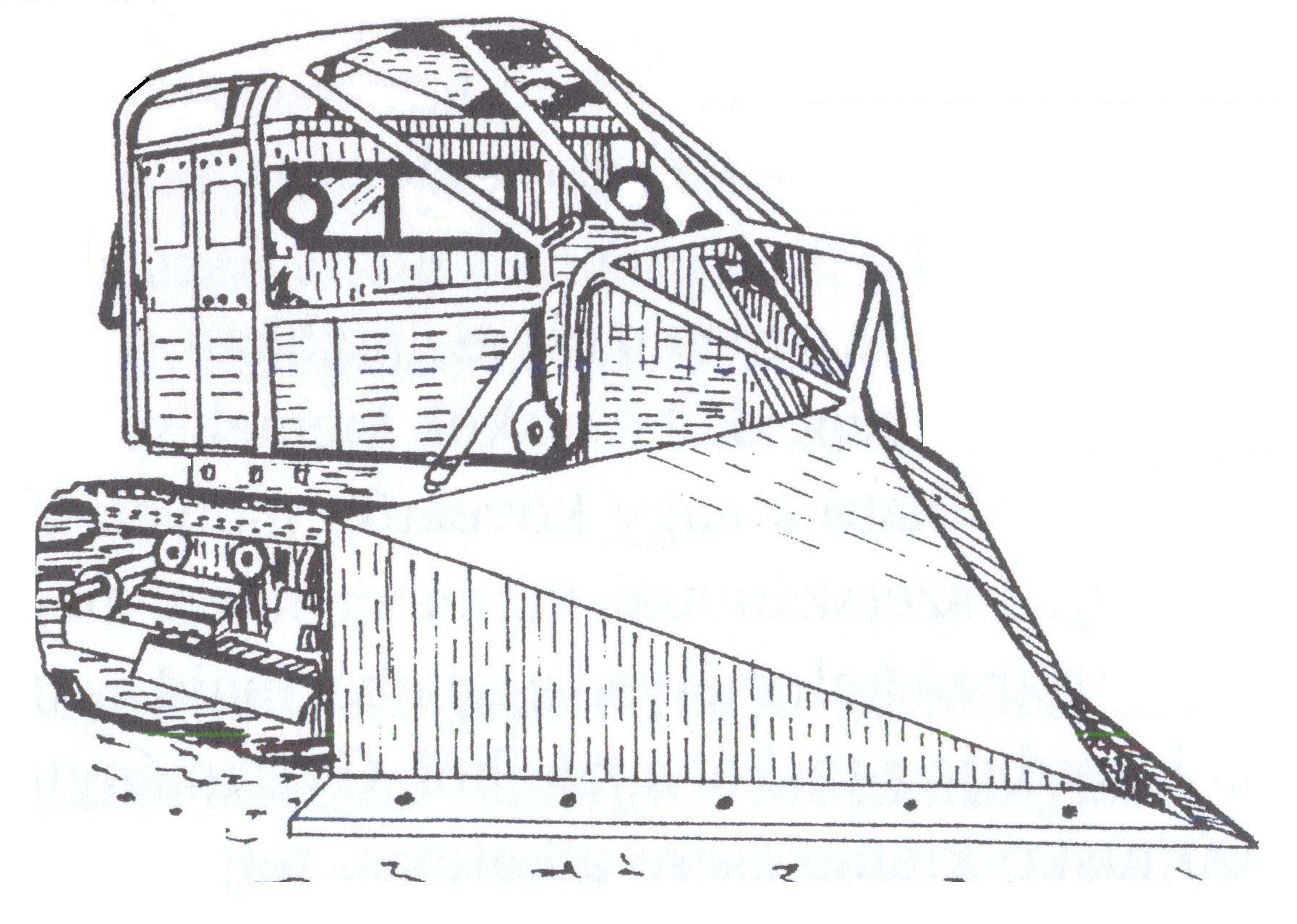
Figure 2.1 Brush cutter
The universal sliding frame is hinged with the engine. A plate with cutting edges, replaceable at the bottom, is mounted slantwise on the sliding frame. These cut the roots. Hydraulic cylinders adjust the cutting depth. While moving forward, the machine’s cutting mechanism shoves the shrubbery and the bushes horizontally to the sides while, at the same time, reaches under them, cuts and lifts them out. The machine’s work width is 2.8 – 3.6m, and its area capacity is 0.3 – 0.5 ha/h.
Machines used in handling stumps
Handling stumps is one of the hardest and greatest energy consuming tasks in field clearing. In the simplest case, a tractor equipped with a cutting edge and a sliding plate may be used. (Figure 2.2)
Figure 2.2 Stump extractor with sliding plate
The task of stump extractors, regardless of the tree type, is to remove big stumps from the soil. Hydraulic versions have replaced earlier used mechanical versions. With these machines, in addition to removing stumps, trees may be felled or the soil may be cleared from bigger stones which may then be transported to a nearby area. The stump is approached by the equipment in reverse. In this position, the machine sinks into the soil. Afterward, by lifting the post and the equipment simultaneously and tilting the post backwards, it removes the stump from the soil. Depending on its make, the machine is capable of removing 150 – 300 stumps in every 10 hours. The engine operates with 75 kW.
Fraises and millers with a diameter up to 500mm are economical. These may be used also for removing stumps left on the cutting area.
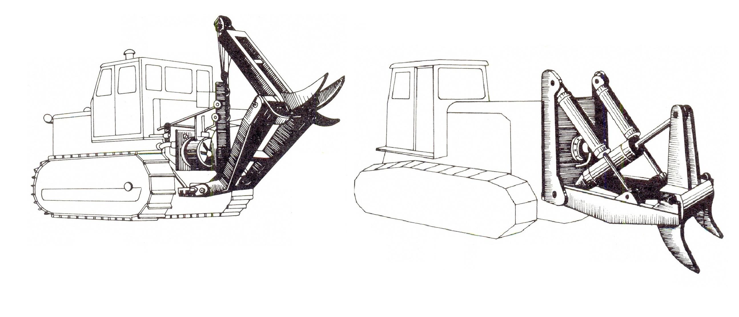
Figure 2.3 Stump extractors
The PTO drives the machine mounted on the tractor’s 3-point linkage hitch system. Its operating element is a short taper screw (Figure 2.4a) which, by penetrating the stump, splits it apart, and the milling disc splinters it. An engine with at least 60 kW is necessary to drive the stump miller (Figure 2.4b) which may be attached with a 3-point linkage hitch. The milling drum is driven via the PTO through the transmission shaft, angle gear, and V-belts.
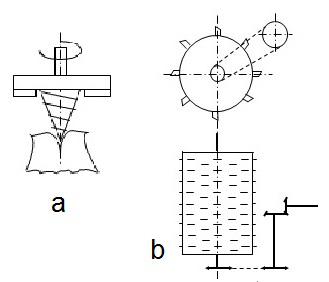
Figure 2.4 Fraise, miller
The machine’s structural specialty is that the milling drum is equipped with milling knives fixed to the milling drum’s mantle enabling them to rotate free around their horizontal axle. The edge of the replaceable milling knives is made of a heavy metal, blunt-proof facing. The knives are installed along a helical line.
The machine’s drum cutting around the stump (Figure 2.5) is driven mechanically via the tractor’s PTO. The drum is made of a plate mantle, with a rim welded to its top. The drum attaches to the driving box through this. The drum may be manufactured in different diameters (usually 500 – 700mm) and lengths (usually 800 – 1,200mm). These dimensions determine the machine’s utilization possibilities. A knife-wreath attaches to the lower part of the drum, with internal and external grading teeth.
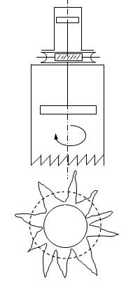
Figure 2.5 Stump cutter
The spiral shaped belt on the drum removes shavings and earth. A hydraulic cylinder operating the ejecting drum – is attached to the top part of the drum. After the stump has been cut around, the ejecting drum ejects the stump heart after having lifted cutter drum and tilted it backwards. A tractor with 60 – 100 kW is necessary to operate it depending on soil compaction and the diameter of the stump. (Horváth B., 2003)
Root rakes
Root rakes (Figure 2.6) are used for removing the roots left in the soil after handling the stumps. The equipment consists of a rigid, closed-profile frame with rigidly attached teeth.
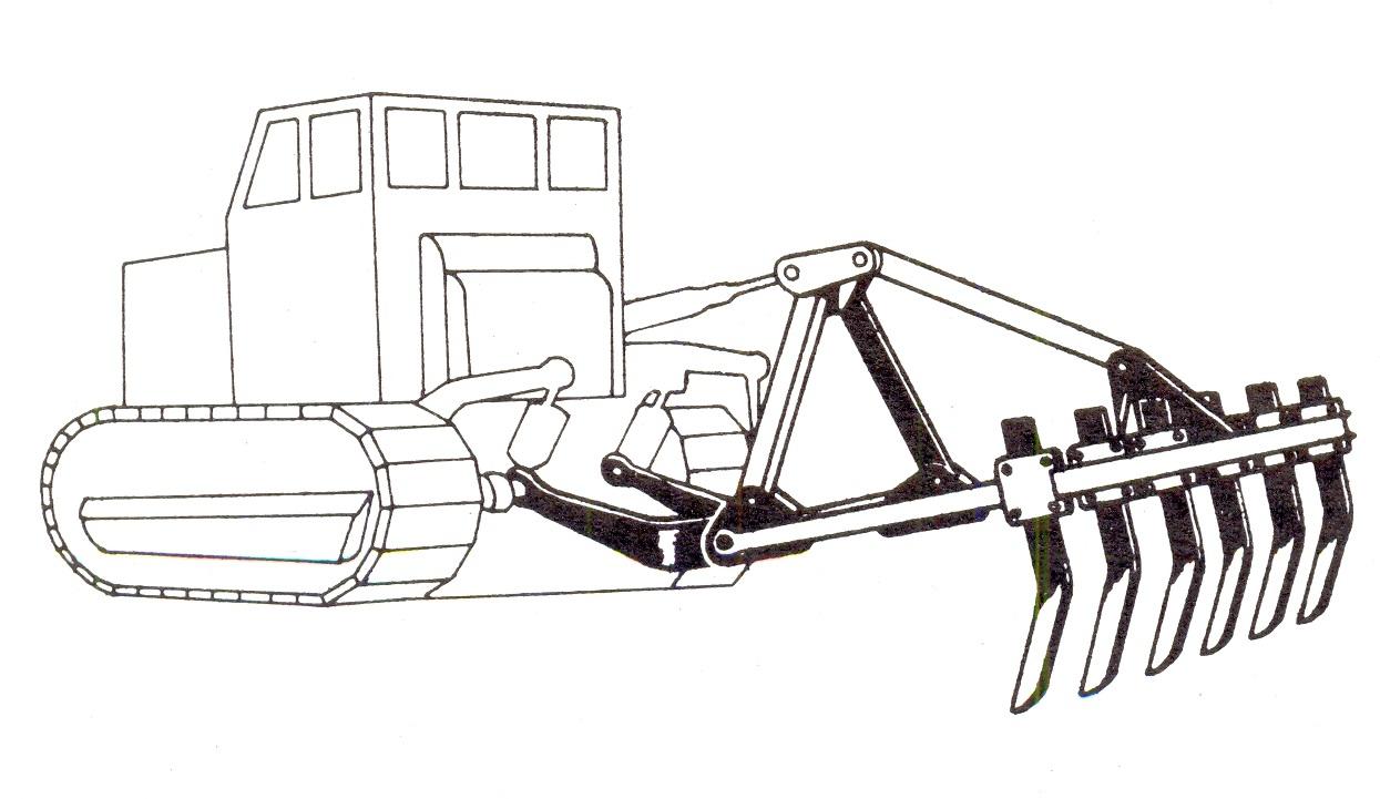
Figure 2.6 Root rake
As the tractor moves forward, the replaceable steel teeth mounted on the beam pull out and collect the bigger roots left in the soil. The teeth working in the soil are chisel shaped. The process is carried out perpendicularly to each other in a 20-40cm depth which helps further work. This machine’s structure is similar to that of the ruter or ripper discussed later. The difference is that in this case they use a greater number of, thus more densely set, ripping knives.
Stone removers
There are two types of stone removers. One type is leaving the stons behind in swath, (Figure 2.7) and the other type with collects them in a container (Figure 2.8). Collecting the stones may be carried out in two phases or in one phase. In the two-phase procedure, in the first phase, the stones are rolled into swath, in the second phase, they are picked up into a trailer equipped with a reel.
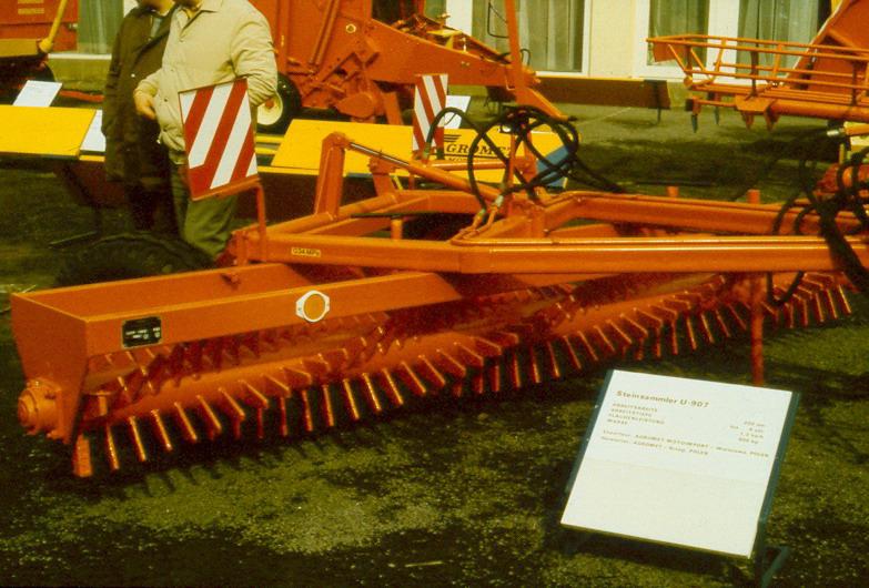
Figure 2.7 Ordering stone remover
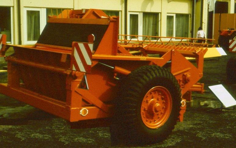
Figure 2.8 Stone remover with a container
When work is performed in one phase, the stone remover puts the collected stones immediately into the container. (Figure 2.9)
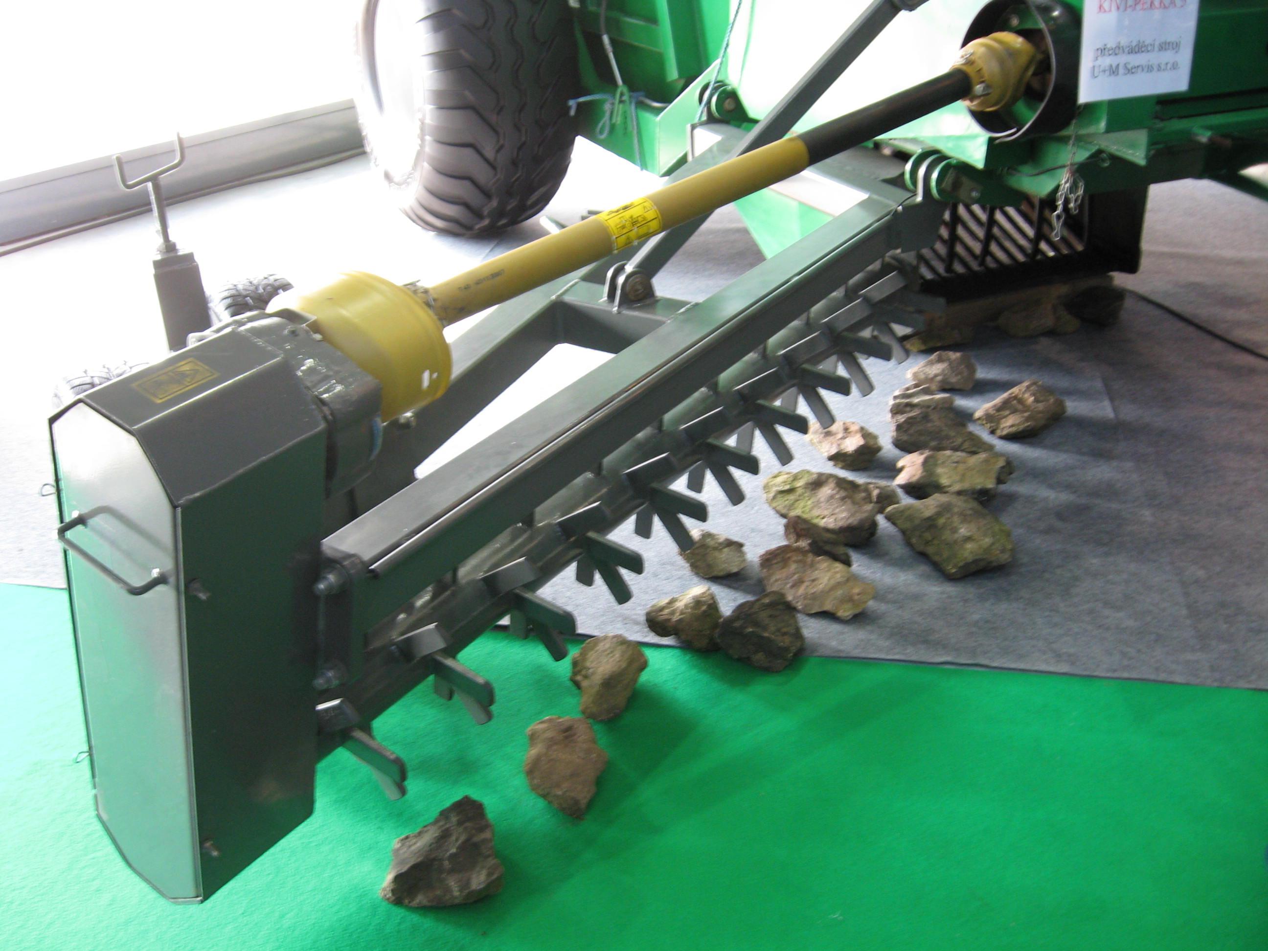
Figure 2.9 One-phase stone remover
The collected stones can be used for marking property borders, building fences or farm roads.
Machines used in landscaping and landshaping
On the field cleared from trees and bushes, the soil is prepared for planting by using equipment designed for landscaping and landshaping. These are machines used for excavating, leveling or incorporation of soil or material similar to soil. From the landscaping machines, primarily earth excavators and transporters are used. There are two groups:
-
machines with a boot or bowl, and
-
machines with cutting edge (plate).
Machines with a boot or bowl collect the scraped-off soil in a container similar to a crate and deliver it to the location of incorporation. One such machine is the scraper.
Machines with a cutting edge roll the scraped-off soil in front of the cutting edge and push it nearby or further away (dozer) or spread it (grader).
These machines must be mobile and have a good maneuvering and turning capability. Their repair and transportation must be quick. In addition, the number of their servicing personnel must be low, and they must be cost efficient and suitable for many purposes. Another important criterion is that they should easily fit into the machine chain.
The theory of soil scraping
The scraper must be moved with specific strength to make sure that the soil scrapings can fill up the bowl following the edge. As it can be seen on Figure 2.10, the scraper’s blade edge’s angle is . The plate of the scraper’s edge is at directional angle to the normal of the soil surface. As a result of the cutting force, the soil compacts, and the scraper plate presses the soil particles in direction FN. When the pressure reaches a certain value, the soil layer splits off at angle depending on the soil condition, composition, shape and setting of the scraper. In order to achieve the smallest scraping force, the force required for scraping at different and angles must be determined. Furthermore, one has to determine the optimal value of angle , resulting in the smallest scraping force. The value of the internal frictional angle among the soil particles changes between = 0°- 45°.
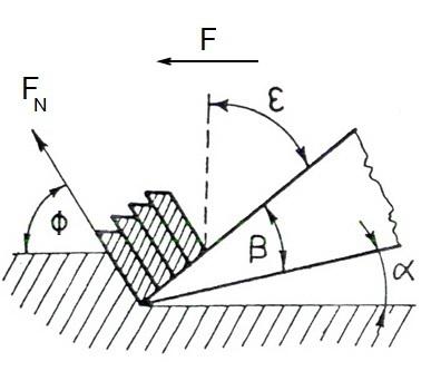
Figure 2.10 Angles characteristic of scraping
During scraping, , the break-off angle of the soil, depends on the quality and condition of the soil, and the shape of the scraper. As Figure 2.10 indicates, when scraping compacted, semi-saturated soil, the shape of the soil parts splitting off in a bending manner below angle is almost like a trapezium. If the soil is very dry and compacted, regular soil scraping cannot be formed. In this case, soil scrapings break off in irregular pieces and, as shown on Figure 2.11, angle may have a negative value. If the soil is soft, because its water content is greater than optimal, scraping may not be characterized with angle , as the soil scrapings break off in continuous ribbons. In case of soil without cohesion, for example, sand, the soil crumbles into grains and collects on the scraper’s blade. Calculations and practical experience prove that the optimal angle of digging-scraping is independent of the frictional angle and its value = 20° - 22° hardly changes.
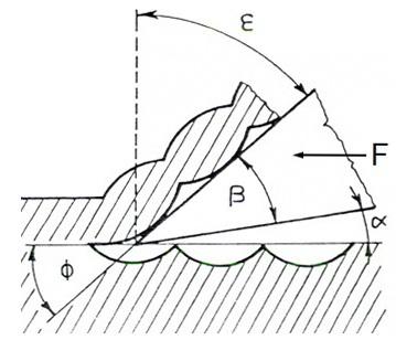
Figure 2.11 Splitting dry, compact soil
Therefore, the plate of the scraper’s blade must be set at angle 20°- 22° to the soil.
The frictional angle has great influence on the scraping force. For example, in case of muddy soil, if the water content decreases from the optimal 20% to 15%, the specific scraping requirement will be almost 7 times greater than in case of soil with normal water content.
If the edge of the blade has a small cutting angle (about = 10°), it blunts very quickly, greatly influencing the size of the scraping force. If the edge of the blade is of 2mm radius originally and, as a result of wearing out, blunts to a 16mm radius, the scraping resistance will be 35% greater. If the tool’s cutting angle is increased from 30° to 50°, the scraping resistance will increase by 20%. The splitting angle must be kept between 0° and 90°. If the soil is hard, the value of approaches 0, but it can also be negative. This may be avoided by using breaking teeth attached to the front of the cutting blade’s edge. The teeth will break up the soil and make it grainy.
In structurally loose soil, where is between 40° and 50°, such as sandy and pebbly soil, using breaking teeth is not economical.
Based on the foregoing, the cutting edge’s angles are arrived at as follows. , the rear angle, should be between 5° and 10°, in order to prevent the friction of the blade against the scraped soil, since this would greatly increase the scraping force. The optimal value of cutting angle is between 20° and 35°, in which case, , the directional angle, will be between 50° and 60°. This is advantageous if the soil is hard and dry, and the blade is made of sheering steel. In case of sculptured soil with optimal water content, cutting angle is between 55° and 65°, because this results in the optimal directional angle, that is when is between 20° and 25°.
On modern machines, they use self-sharpening blades, the so-called sandwich steel blades. The lower plate is extremely hard (alloyed), but thin, and the upper plate is made of thicker, durable steel. During scraping, the upper plate continuously wears out, but the lower thin, hard steel plate (resistant to wearing out) does not allow the blade to blunt. If the blade’s edge is not perpendicular to the direction of scraping, but tilted (side angle < 90°) (Figure 2.12), then the change in the scraping force is a parabolic function according to the diagram shown on Figure 2.13 and at = 45° the decrease in the specific scraping force is only 10%.
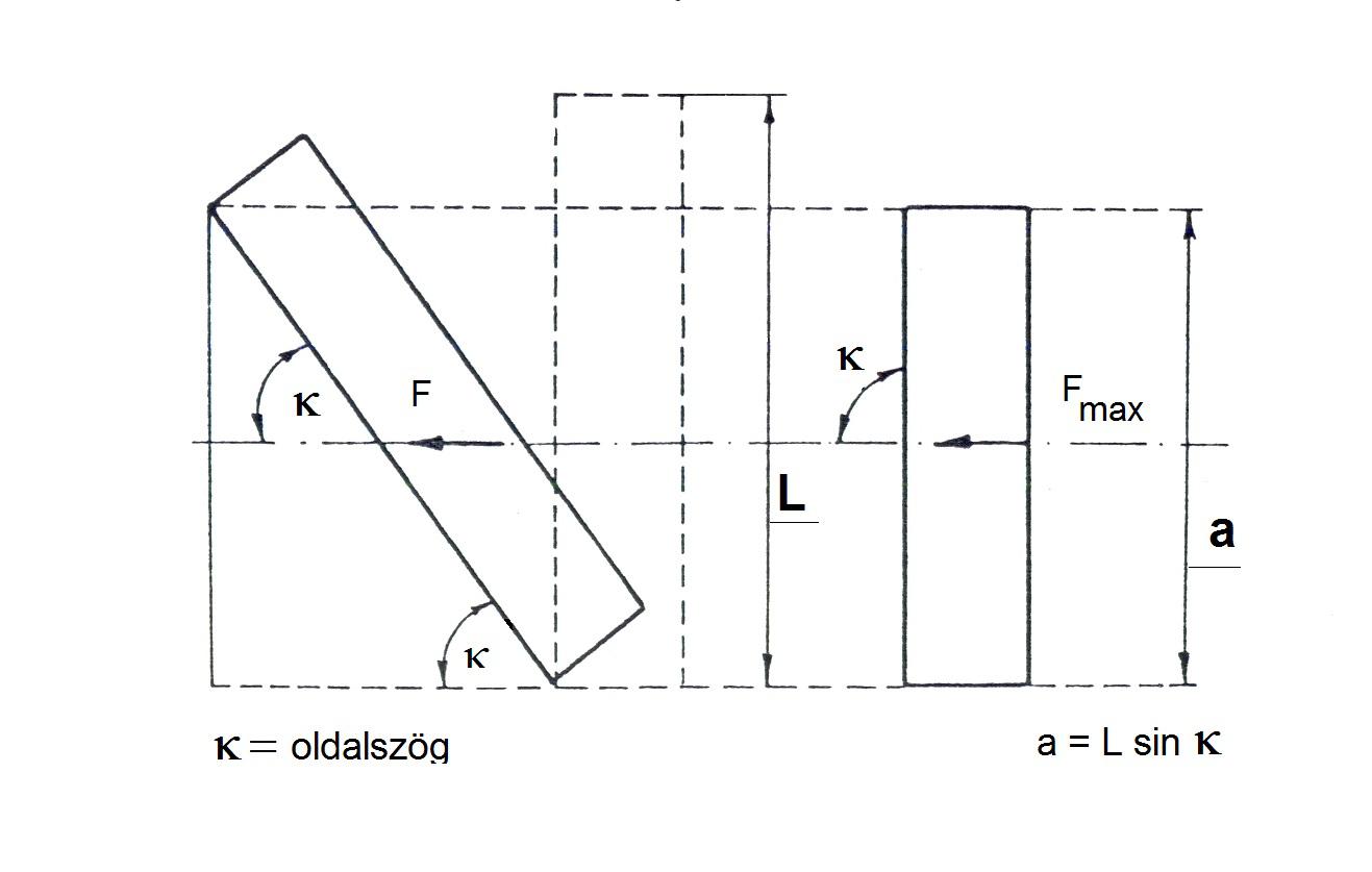
Figure 2.12 Tilted scraping edge
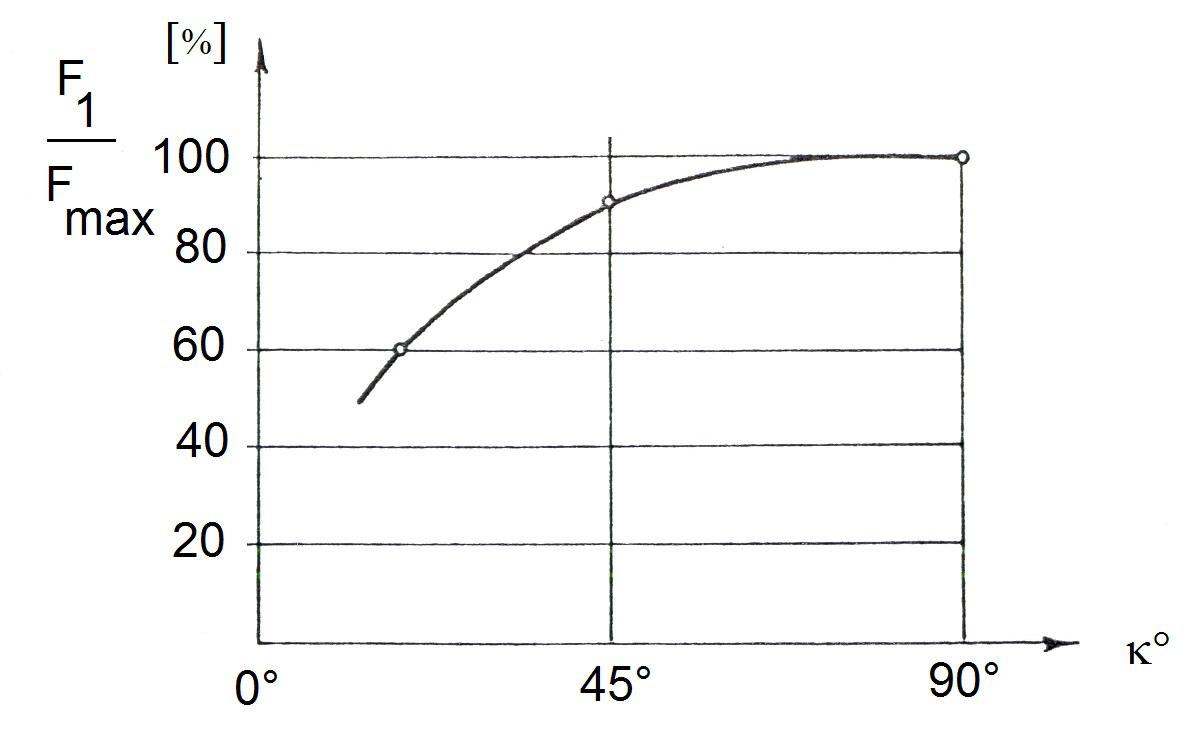
Figure 2.13 Decrease in scraping force as a function of the side angle
The scraped-off soil scraping must slide on the blade’s plate and later inside the scraping bowl on the bowl’s walls shaped and surfaced so as to comply with the laws of flow. The smooth metal surface has much greater resistance than rough or wavy surfaces.
The blade must be free of protruding screws, rivet-heads, or indentations, because behind or in these the soil gets in the flow’s shadow and sticks. In order to determine the shape that complies with the laws of flow, first the flow speed must be determined. The flow speed and the flow’s pressure must conform to the profile’s curve. The more concave is the profile, the harder is the flowing soil scraping squeezed and forced to flow along the wall, for example, upwards.
The scraping force characterized with a simplified equation:
F = a . b . p (N)
a – the thickness of the soil scraping, cm,
b – the width of the soil scraping, as well as the length of the scraper blade, cm, and
p – the specific scraping resistance of the soil, N.cm-2.
If the soil work machine cannot provide the required F towing power, because p, the specific scraping resistance, increases, one must decrease the thickness of the soil scraping, but never the speed of the scraping.
The scraping speed should be high rather than low. The scraping’s power requirement does have an optimal speed. On the curve on Figure 2.14, the maximum towing power is achieved when the speed is very slow.
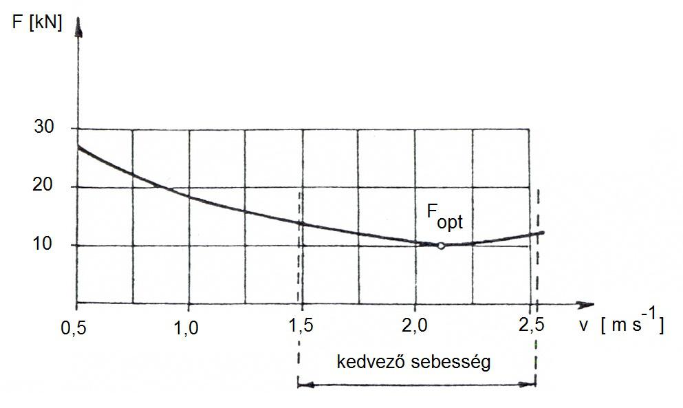
Figure 2.14 Scraping power as a function of speed
Even if the scraping blade is towed at a speed higher than the optimal speed, the towing power will increase by only about 24%. Therefore, it is advisable to increase the excavator’s scraping speed up to the technological limit, if necessary, even by pushing the machine, because, as the scraping slows down, the machine may easily throttle down and stop. (Karai - Horváth 1992)
Scrapers
Among the soil work machines, almost without exception, only the scraper is capable of performing complex work processes. Set forth below is the usual work order of moving soil:
- breaking up and scraping the soil,
- lifting the material,
- putting it into the transportation equipment,
- delivering it over the required distance,
- spreading it in layers with the appropriate or required thickness, and
- compacting the earth moved
The scraper performs these tasks all by itself.
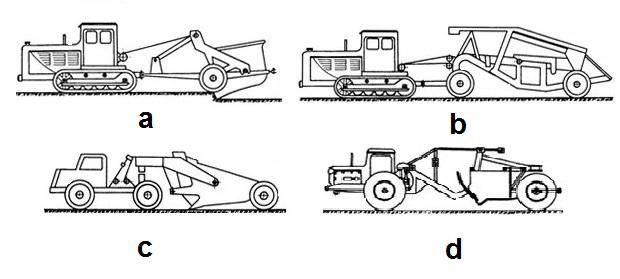
Figure 2.15 shows the different types of machinery.
Figure 2.15 Scrapers
a – one-axle towed scraper, b – two-axle towed scraper, c – saddled, d – self-propelled
The two-axle towed scraper is the best known mid-sized type. Most self-propelled scrapers (Figure 2.16) are supplied with rubber tires; caterpillar types are rarer. Its working tool is a bowl equipped with a cutting-edge, supported by one or two axles. The bowl is hinged with the frame. Most often, it is steered mechanically or hydraulically.
The bowl is welded of steel plates, and its sides are stiffened by U steel welded on from the outside. The bowl’s front wall consists of a swinging door, while its rear wall consists of a sliding door. The scraping blades are mounted on the front of the bottom plate. Usually there are three scraping blades, and as they do not blunt at the same rate, not all blades are replaced or sharpened at the same time. Also the breaking teeth are placed here. A short side knife is fixed to the bottom part of each of the two side plates, with which the side plates of the lowered crate can also scrape the soil.
The scraping angle is adjusted depending on the extent of compaction and saturation of the soil. The scraper’s work consists of scraping, transportation, emptying, and returning to the location of the scraping.
Scraping requires two or three times greater towing power than transportation. During scraping, as the crate is being filled up, the need for towing power can increase to such a degree that the machine throttles down and stops. To help the scraper, a dozer may be attached to it; the scraper’s rear frame is designed to enable such attachment. The two machines together can overcome the problem described. Usually, one dozer is sufficient for 4 – 6 scrapers.
After scraping, transportation must be carried out over the shortest possible distance and at the greatest possible speed. Depending on the transportation distance, machines have different crate volumes. Crates with a volume less than 3m³ are used on a distance between 50 – 300m, crates with a volume of 6m³ on a distance between 100 – 400m, towed crates with a volume of 9 - 10m³ on a distance between 300 – 700m, and crates with a volume exceeding 10m³ are used on a distance between 700 – 2,000m.
Emptying is performed by forced emptying (the sliding plate in the back of the scraping crate pushes out the soil) or semi-forced emptying (the tilting mechanism of the scraping crate throws out the soil), while, in case of smaller machines, it is done by free emptying (the soil is thrown out simply be turning it over). In this phase, the machine dumps the delivered earth into the indentations. In case of free emptying, the mounds of soil left behind must be flattened by other machines, for example, by dozers.
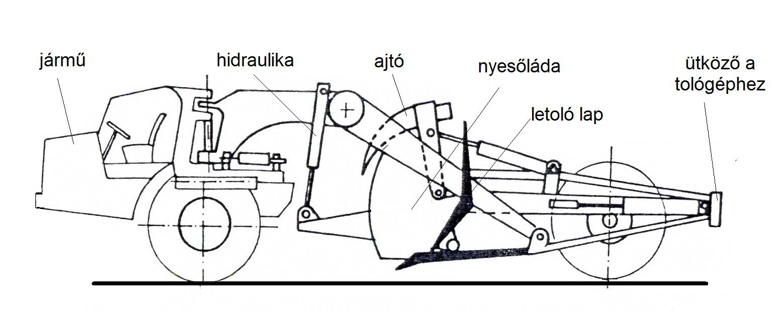
Figure 2.16 Hydraulic self-propelled scraper
In idle runs, the scraper is elevated to transport position. The scraper should return to the scraping location quickly, using the shortest way to decrease the cycle period and to make work more efficient and economical.
The one-axle scraper is also towed by separate power unit. Its advantage is that it is 2 – 2.5m shorter than the previous type. Consequently, even in a tight space, it turns easier than the long, two-axle towed scrapers. If the power unit is supplied with pneumatic rubber-tire, it may move with a higher speed than the caterpillar type, namely with 20 – 25km/h. A scraper moving with such speed is economical even if it transports over a distance exceeding 1,000m. During scraping, this type also requires pushing, because the tractor’s engine is not designed to cover the excess work of scraping. This scraper’s technology, filling and emptying functions are the same as those of the previous types, but it is much more mobile. (Horváth B. 2003)
Figure 2.17 illustrates the machine’s moving methods.
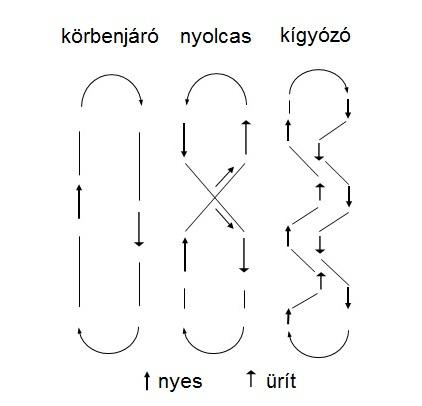
Figure 2.17 Moving methods of scrapers
The scraper which moves on a circular (or elliptical) path is used on greater distances. Its disadvantage lies in the many round-trips and idle runs. Therefore, it is better to operate the scraper in a winding manner or following the form of the number eight. In the latter case, the fully loaded scraper does not have to make sharp turns. In addition, in one full round-trip, two scraping and two emptying tasks can be performed and higher speed may be achieved. Therefore, the entire work process is more economical.
Graders
The graders, while moving ahead, scrape and grade the earth. Two main types are known, the towed and the self-propelled, motorized graders. Some towed graders are also equipped with an engine. This makes steering and the adjustment of the grading knife easier, but plays no role in the towing itself. The grader is used mainly for finishing types of earth work, only rarely for moving earth for production. It grades the crown of the bank, the sole of the indentation, the ditch, and the bank of the indentation according to the required profile, most often after the completion of soil compaction. Occasionally, it hoes the earth on a big area, sweeps aside the humus layer, thereby preparing the field for soil work.
The tool of the grader is a big, concave grading knife, and is somewhat similar to the sliding plate of the dozer. The grading knife may be set to all three main directions. (Figure 2.18)
The grading knife is attached to the frame, the position of which can be adjusted by hydraulic cylinders. A hydro-motor driving a big cog-wheel can adjust the grading knife’s angle to the travel direction. After having turned back the grading knife completely, the breaking teeth may be turned down. With this knife position, frozen earth surface and old, bad roads can be broken up. The frame is a rigid, welded steel structure or a beam bent and welded from square pipes. The grading knife, the steering equipment, and the wheels are mounted to the frame. As the machine operator can see the grading knife from the cab, he can accurately direct work.
The four wheels are supplied either with iron hoops or with pneumatic rubber tires. The wheels are not spring loaded, as the movement of the spring would result in a wavy surface.
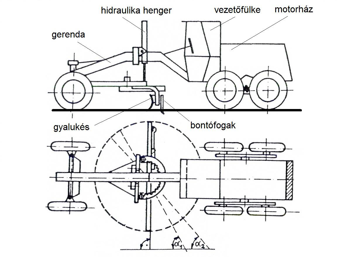
Figure 2.18 Motorized grader
The tilt and height of the wheels, the relationship of the frame and the wheels may be changed significantly. Sometimes a wheel on the one side runnes in the ditch, while another wheel on the other side moves on the bank.
A diesel engine unit pushes the motorized grader from behind. It does not necessarily have to be always in the back, because if, for example, there is not enough room for turning around, the grading knife is turned and the grader is towed by the engine being now in the front. Modern graders are, without exception, equipped with engine.
Dozers
The basic unit of the dozer is the great adhesion caterpillar or rubber-tire tractor (Figure 2.19). Most often, the two sliding shanks hinge with the bridle which also hinges with the chain frame or the chassis of the tractor. The dozer plate, with adjustable tilt and slant, is mounted on the end of the sliding shanks.
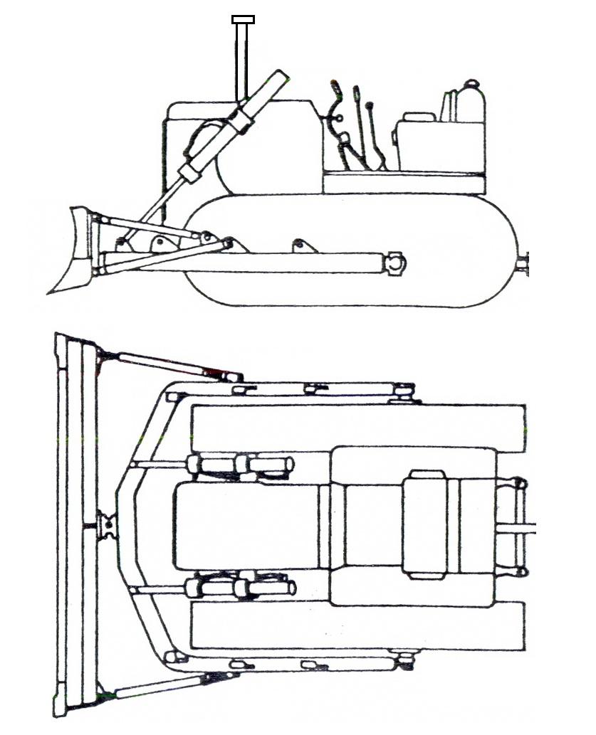
Figure 2.19 Dozer
Dozers with dozer plates which cannot be turned in the travel direction are called bulldozers, capable of moving only up and down. The dozer plate is a 2.5 – 3m long and 0.8 – 1.2m wide concave steel plate stiffened by a skeleton on its back. The two main flanges, to which the sliding shanks attach are such that, with the supporting bars of the sliding shanks, the concave dozer plate can be adjusted at different scraping angles (cutting angle) in accordance with the soil’s internal friction.
While the dozer is moving, the machine operator lowers the dozer plate into the ground. Then the scraping blade fixed to the bottom edge of the plate scrapes out earth shavings, which pile up on front of the plate. If the dozer plate’s perpendicular segment is shaped so as to satisfy the laws of flow, the earth shavings will flow upward in front of the plate and roll up during movement. The dozer pushes the soil as long as soil work and transportation require it. The dozer should be operated on short distances, as a portion of the rolled earth will be left behind at the sides of the plate. In order to avoid this result, in case of some dozer plates, the two ends of the plate are closed by welded side plates.
In earlier versions, the dozer plate was placed directly under and in front of the cooler of the engine. In newer versions, the engine and the cooler are mounted on the rear of the machine. As the driver sits closer to the dozer plate, he can better monitor the plate’s scraping and rolling functions.
During hoeing, when only a thin layer must be scraped and deposited on the side, the dozer plate is set at an angle, usually 45°, to the travel direction. The scraping resistance decreases if the side angle increases. If the sliding plate’s angle is 45°, the scraping resistance is merely 85 -90 % of the 90° frontal resistance.
Machines loosening the earth
The simplest machine used for loosening is the ruter or ripper. (Figure 2.20) One to three steel ripping knives are embedded in a strong and heavy, welded or steel moulded frame. The machine is towed by a caterpillar tractor or a road roller, but always by heavy self-propelled vehicles. The end of the ripping knife close to the earth is pointed, or sharpened and shaped as a triangle. These characteristics enable the ripping knife to break up the earth at the appropriate cutting angle.
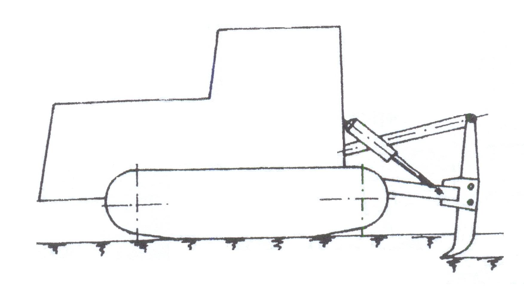
Figure 2.20 Ruter or ripper
The ruter or ripper has many functions and can be used for a variety of purposes. On cleared fields it rips out roots, while on heavily pebbly soil it loosens stones, and so on. These tasks are of preparatory type; they make scraping easier for the other soil tillage machines.
Machines for smoothing and leveling the surface
The micro-topography of the soil surface greatly influences the yield of the different cultures, especially on irrigated areas. Conditions enabling even soil saturation and thereby even plant development can exist only on appropriately smoothened and leveled areas. On such areas, also irrigation demand can be decreased and the soil tillage machine’s area capacity can be increased.
Leveling and smoothing may be justified even if incorrect cultivation, gullies, deflation, and indentations resulting from the treading of tractors and agricultural machines make the surface uneven. Regular leveling work is necessary in certain types of cultivation, for example, in seedbed and direct sowing cultivation. The machines used for leveling and smoothing may be classified as follows:
-
short levelers,
-
levelers with big axial distance,
-
smoothing sledges, and
-
simple smoothing units.
Short levelers are suitable for rougher leveling of bigger, 30-60cm, level differences, and uneven surface within a short distance (4-5m). There are mounted and semimounted versions. Figure 2.21 shows a mounted version. Its deflecting plate may be set by a two-position hydraulic cylinder around the vertical shaft and by a spiral spool around the horizontal shaft, depending on the work required.
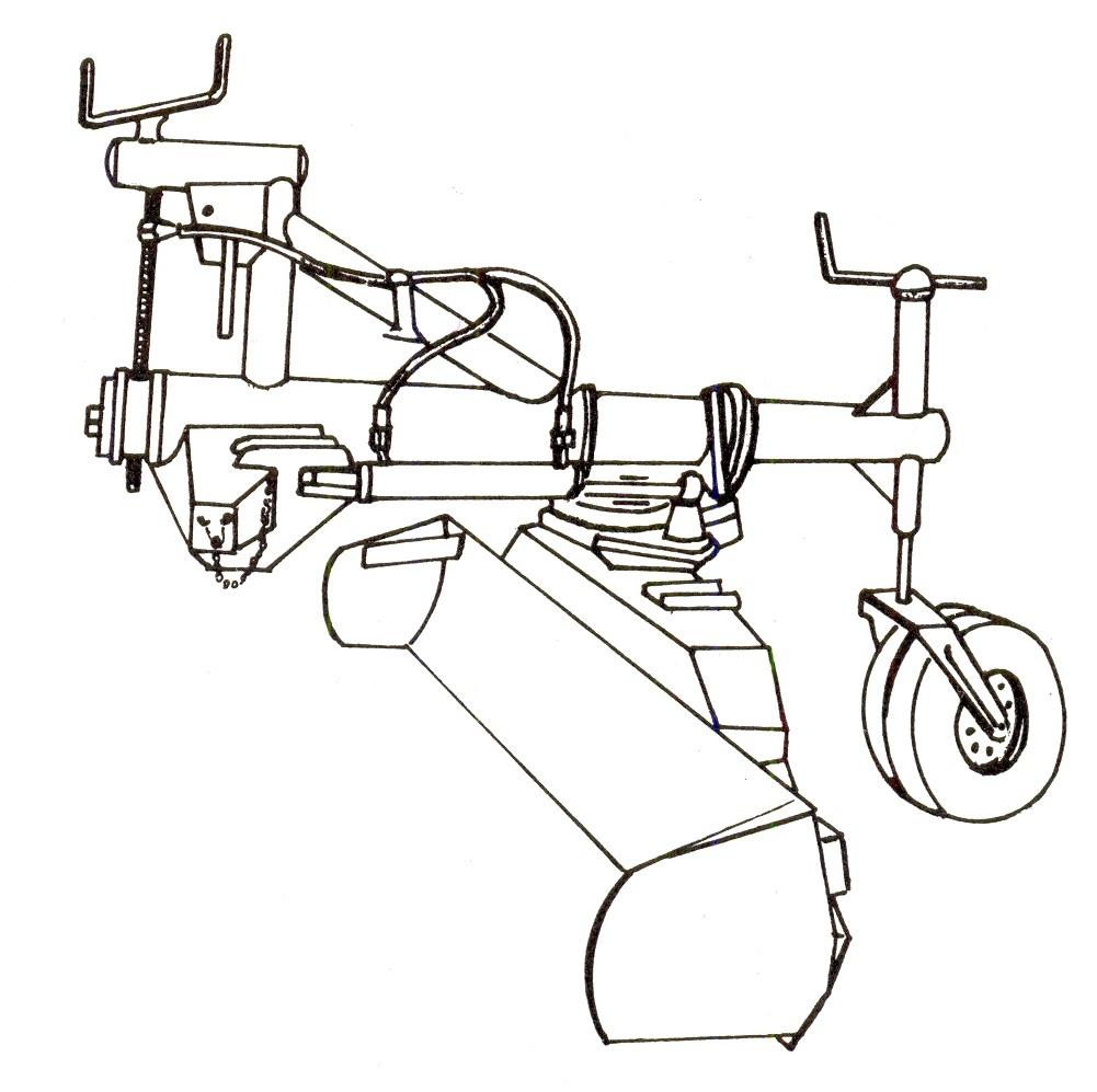
Figure 2.21 Leveling machine
Depth limiting wheels placed behind the closed plate adjust the cutting depth. During leveling, their angle is usually 90°.
The semi mounted types are equipped with a hydraulic cylinder responsible for setting the working depth and turning the machine into transport position. The depth limiting wheels are placed on the two sides of the plate, thus, at the bottom they may also function as open scraping crates. In case of the fully towed types, the plate’s angle is not adjustable.
Using levelers with big axial distance (Figure 2.22) is justified if the accuracy of leveling must be within 3 - 5cm. Only the 8 – 20m long levelers meet this requirement.
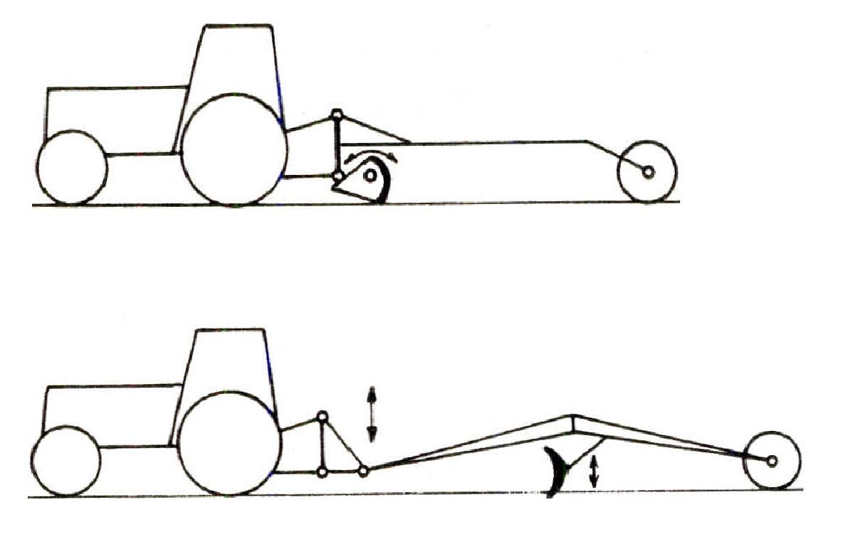
Figure 2.22 Levelers with big axial distance
This leveler is economical only if the unevenness does not exceed 30cm and the soil is loose, because, as a result of the shallow scraping depth (5-8cm), the number of leveling runs increases. If working conditions are highly unfavorable, scrapers should prepare the soil.
Smoothing sledges are used for the final leveling of smaller unevenness. 4-5 leveling elements are embedded in a rigid frame, positioned vertically one after the other with a determined degree of staggering, so that the first elements are placed higher than the ones following them. They work a 2 – 5m wide, 6 – 10m long area. Towing requires a 60 – 80 kW tractor.
Simple smoothing units are used on cultivating machines and equipment preparing seedbeds. Their primary task is cross-directional leveling.
Soil compacting machines
These may be used primarily for work on farm roads and other dirt road constructions, and their maintenance. They operate on static or dynamic principles. The compacting effect of static machines is the result of their own weight as they roll on the surface. The machines operating on the dynamic principle achieve the appropriate level of compacting by ramming and vibration. These are used mainly for compacting soil layers of smaller surfaces.
Soil tillage machines in the plantation cultures
The purpose and tasks of cultivation and maintenance
Cultivation includes all acts performed in respect of the plantation’s soil such as soil preparation preceding planting, soil turning, application of fertilizers and soil disinfectants, crumbling, loosening and deep-loosening, while maintenance includes the works carried out on the soil surface, like chemical weeding, soil covering, treatment of cover crops, and utilization of the chopped scrapings.
In today’s plantation cultures, grassing, soil covering, and weeding using environmentally friendly chemicals serve the purpose of minimum tillage.
The most important aim of cultivation is the creation and maintenance of favorable physical, chemical, and biological conditions for the soil. For purposes of cultivating the soil, especially selecting the correct cultivation depth, one has to be familiar with the developmental and location characteristics of the roots, but precipitation and the degree of soil compaction must also be taken into consideration.
Cultivation procedures
There are three basic cultivation procedures in the plantations:
-
mechanical cultivation (fallow or open),
-
soil covering cultivation, and
-
chemical weeding.
In practice, these methods are usually applied in a certain combination. Soil treatment includes inter-row and row cultivation.
Mainly, the soil preserving covering cultivation method meets the requirements. Chemical weeding may be used only within limits, as a supplementary method. Ecological and topographical conditions play a significant role in determining and influencing the possible cultivation method.
Mechanical cultivation supplemented with chemical weeding is the most wide spread cultivation procedure in Hungary. In practice, this procedure is called fallow or open cultivation method. In inter-rows, neither green manure crops nor grass types are grown, and the rows are not covered.
The usual cultivation depth is 8-15cm, because the more deeply the soil is cultivated, the greater is the loss of moisture. The best approach is to use cultivators, since they loosen the soil, do not compact it too much, and the least destroy the soil structure.
In the course of mechanical cultivation, the rainy weather makes driving on the loosened soil and the performance of the next steps difficult. Consequently, from the middle of the summer, instead of cultivation, mowing and mulching are used for regulating weed in inter-rows.
Organic fertilizers and fertilizers containing phosphate and potassium are applied to the soil during the fall mechanical cultivation work. For incorporation of organic fertilizers, digging machines, while for the incorporation of phosphate and potassium fertilizers, heavy cultivators can be used.
Plowing is not necessary nor is it recommended for cultivating plantation cultures. However, on plantations where the soil is more compact, loosening should be done in the fall in order to loosen those layers which are deeper, more compact, and not well aerated. Subsoil may be loosened twice a year 40 – 60cm deep, depending on the condition of the soil. This procedure, however, always greatly damages the roots. Consequently, for safety reasons, only inter-rows are loosened, 100-150cm far from the trunk. (Soltész 1997)
Soil tillage machines in use
In plantations, passive, semi-active and active cultivation equipment is used. Depending on the technological requirements, we distinguish shallow and deep cultivation.
Passive tillage machines are used primarily to loosen the soil, influence capillarity, and regulate the growth of the plants. Their performance requirement depends on their towing resistance. The circumferential force arising from the tractor’s wheels must overcome towing resistance. On sloping areas, especially moving uphill, also the climbing resistance must be surmounted. In case of passive tillage machines, this could lead to significant machine slippages damaging the soil in the wheel tracks. Therefore, for physical reasons, the use of passive tillage machines on slope is limited. Only changing the speed can influence work intensity.
Plough
If plowing is necessary, various equipments may be used. On grape plantations, where inter-row does not exceed 1.3m, ploughs which turne in two directions can be used. In bigger inter-rows, supplementary (filler and opening) plough heads may be applied. On grape plantations where covering is used even today (for example, on young plantations in order to protect the grafting from frost) work is done only by filler plough bodies mounted on the side. Inter-rows are cultivated by deep-looseners. Both the plough and the deep- loosener can be mounted on the same frame.
Looseners (light cultivator, chisel plow, deep loosener)
In inter-row cultivation, looseners and their variations are the most often used toillage machines. They are utilized especially during the spring and fall cultivation work. Their task is to loosen the soil, thereby decreasing evaporation, and to stop the proliferation of weeds. Their frame usually comes in multi-holder style, but it may also come in a main-holder style. The rigid or spring loaded chisel plows are mounted on the frame, to which different elements may be attached depending on their shape or application (Figure 2.23).
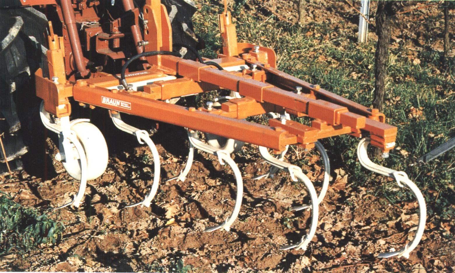
Figure 2.23 Chisel plow
More recent cultivator frames are mostly shorter, their own mass is greater, and, in case of semi mounted linkage, most of their weight is on the rear axle of the tractor, increasing its towing power. They are used without depth limiting wheels. A clod-crushing harrow fixed to the frame’s end and the towing resistance’s regulation assist in guiding the cultivator at a specific depth and setting the required working depth. Greater working depth, coupled with better stability, make both shallow and deep cultivation possible. Consequently, deep looseners are not necessary.
Following practical demand, looseners as basic cultivating machines are often transformed into universal cultivators by attaching supplementary equipment. Other tillage machines such as rotary cultivators, rotary harrows or disc harrows are mounted on the cultivator’s frame. Therefore, these machine combinations may also be called pre-cultivating combinators, as Figure 2.24 indicates.
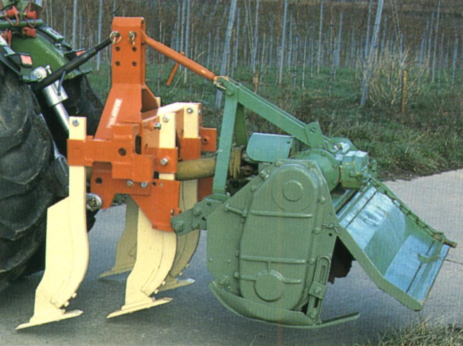
Figure 2.24 Prep-cultivating combinator supplied wit a rotary cultivator
Disc Harrow
The disc harrow (Figure 2.25) is often used on flat plantations for carrying out spring and summer work. It loosens and crumbles the soil and chops and incorporates weed into the soil.
The disc harrow is supplied with concave discs made out of a portion of a sphere mounted on the axles at a tilted angle to the travel direction. The concave side of the disc faces the travel direction.
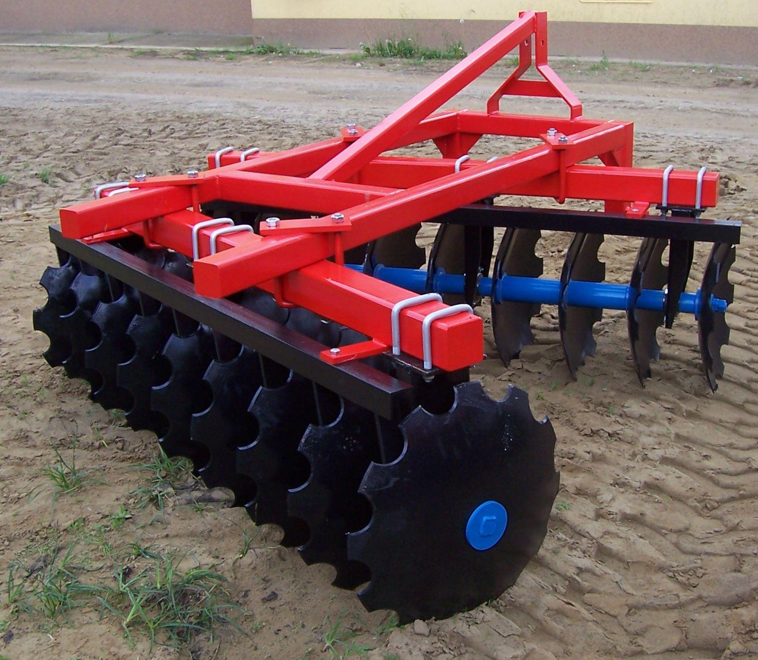
Figure 2.25 Disc harrow with jagged discs
The rolling discs move the soil on their inner side upwards and perpendicularly to the travel direction. By adjusting the angle to this, the chopping and mixing effect can be improved and the towing power will increase. Often additional weights are applied for the purpose of increasing retraction power and the cultivation depth of the discs.
The axles of the discs stand mostly in pairs, in a V shape. Occasionally, they are placed in groups of four in an X shape so that the resulting side forces balance each other’s effect. The slanted position of the axles can be changed, allowing the angle set to the travel direction to be adjusted. This angle must be at least 20º if the discs are to penetrate the soil. This same angle prevents the discs from reclining on their back side, and helps them rolling on their own. The self-sharpening discs may come with smooth or jagged edges.
Rotary spade-harrow
Their use on plantations is not wide-spread. (Figure 2.26)
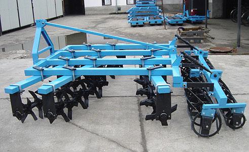
Figure 2.26 Rotary spade-harrow
They are used under extreme soil conditions, mostly in a combination with disc harrows. The star shaped cultivating knives are mounted similarly to the disc elements. They sink into the very pebbly or compact soil as a result of their own weight, facilitating the breaking up and cultivation of the soil. Spade-harrows must be towed with a great speed to ensure appropriate work quality. They leave a rough soil surface and do not reach the roots of the weeds sufficiently. Their great advantages are that their cultivating speed is higher than that of the disc harrows and they are not sensitive to pebbly soil.
Rollers
Reollers are used on plantations as final tools in equipment combinations. . They level the soil, assist in maintaining the required cultivating depth, and ensure soil compaction at the time cover vegetation is sowed. In inter-row cultivation, the following machines are preferred:
-
plain rollers, and
-
clod crushing rollers.
The lighter rollers are of cage type or toothed packer.
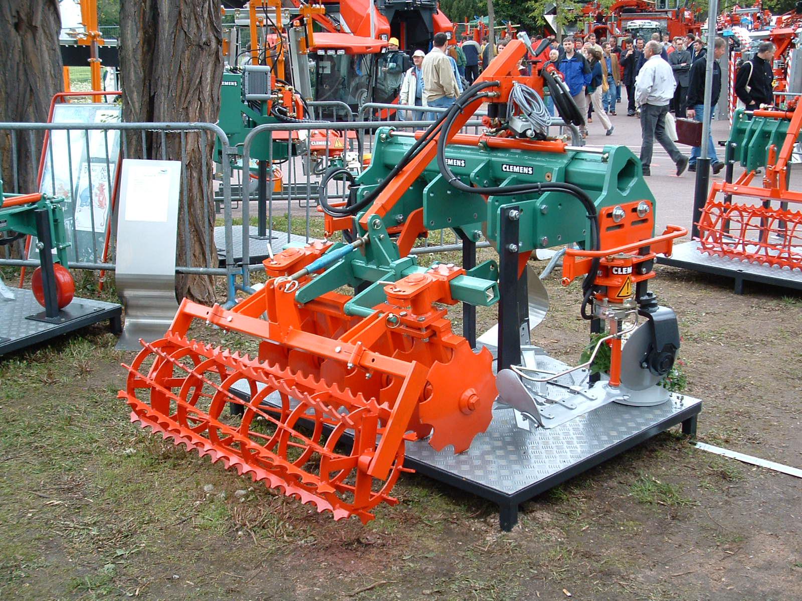
Figure 2.27 Cage type toothed packer
Cage type toothed packers consist of square-segmented sticks positioned on edge and placed along a spiral line with a wide thread elevation. These can be used for many purposes. Also rollers with tine-bars are suitable for different tasks, because if the soil is loose their compacting result is good, and if the soil is compact their crumbling function works. Two structural versions are sold:
-
rollers with tine-bars placed along a spiral line, and
-
rollers with straight crumbling sticks.
For crumbling the soil, crumbling rollers are used. The downside to this approach is that, on wet soil, they quickly clog up. Clod crushing drums are less exposed to this problem. The Cambridge and cross kill rollers have lived up to expectations very well. They leave a lumpy surface, thereby decreasing erosion risk. On plantations, the creation of a fine-grained soil surface is not the goal (Figure 2.28).
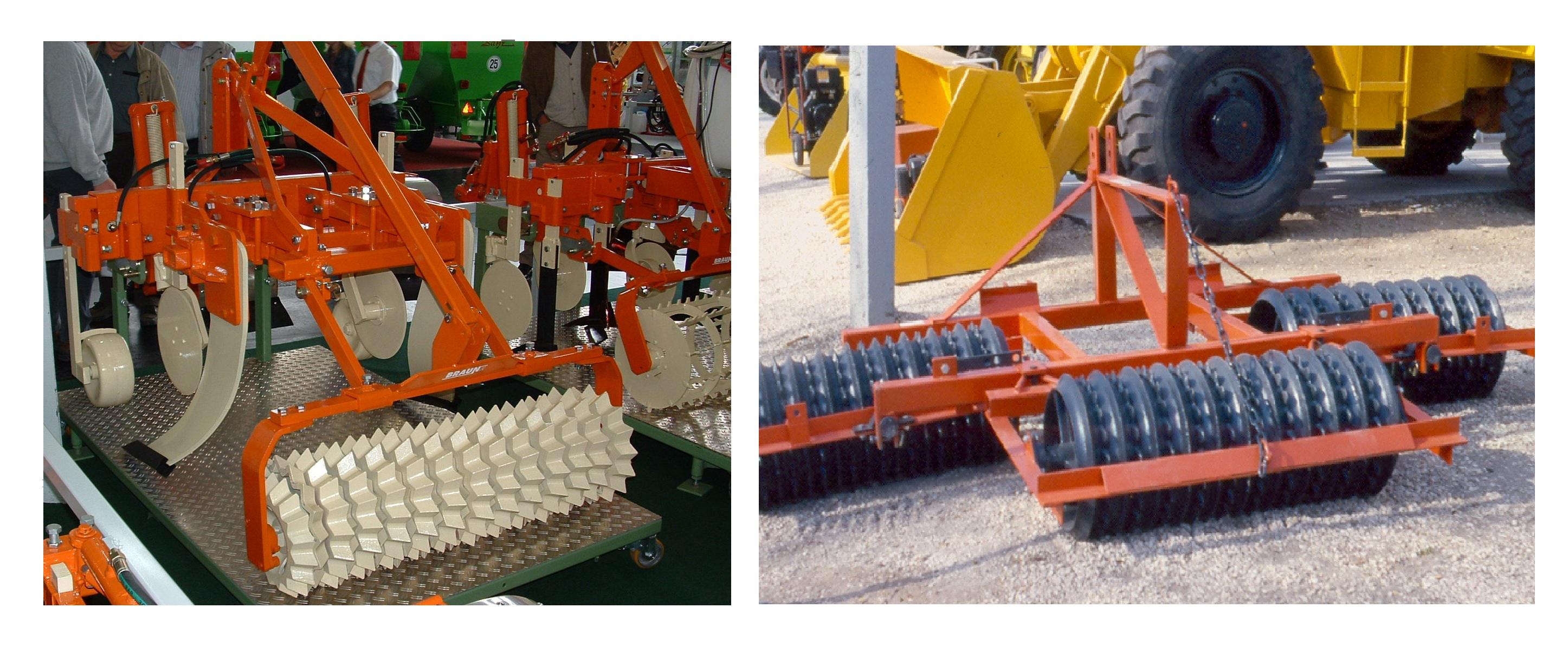
Figure 2.28 Cross kill and Cambridge rollers
Driven, active cultivators
The active cultivators get their driving power via the transmission shaft. The circumferential force on the tractor’s driving wheels decreases compared to towed equipment. As the tractor’s engine power is transferred to the soil with great efficiency (80-90%), which is only about 70% in case of hauled equipment, on slopes climbing capacity will suffer a smaller loss and less slippage. Therefore, driven tools, regardless of the travel speed, can easier adjust to current requirements (for example, incorporating fertilizers, soil loosening, chopping plant remains). The equipment’s travel and cultivating speed determine work efficiency.
Compared to towed equipment, their disadvantages are that they are more expensive, their working speed is lower, and they wear off quicker.
The rotary cultivator is the most often used active tool (Figure 2.29). If used too often, the danger arises that the soil structure will be damaged, a compact sole layer will result, and the risk of erosion will increase.
For the purposes of changing the rpm of the rotor, the rotary cultivator is supplied with spare-wheel drive or cog-wheeled gear. In case of two cog-wheeled gears, the circumferential speed is usually set to an rpm between 150 and 280. Drive is delivered via the PTO and with the help of the transmission shaft to a cone cog-wheel gear which transfers the power directly (in middle drive) or through a side gear with a chain or cog-wheel drive to the rotary cultivator’s axle.
Sliding skids or support wheels determine their working depth. In order to avoid overcharge during the drive, a safety device is built in (for example, an axle safety switch).
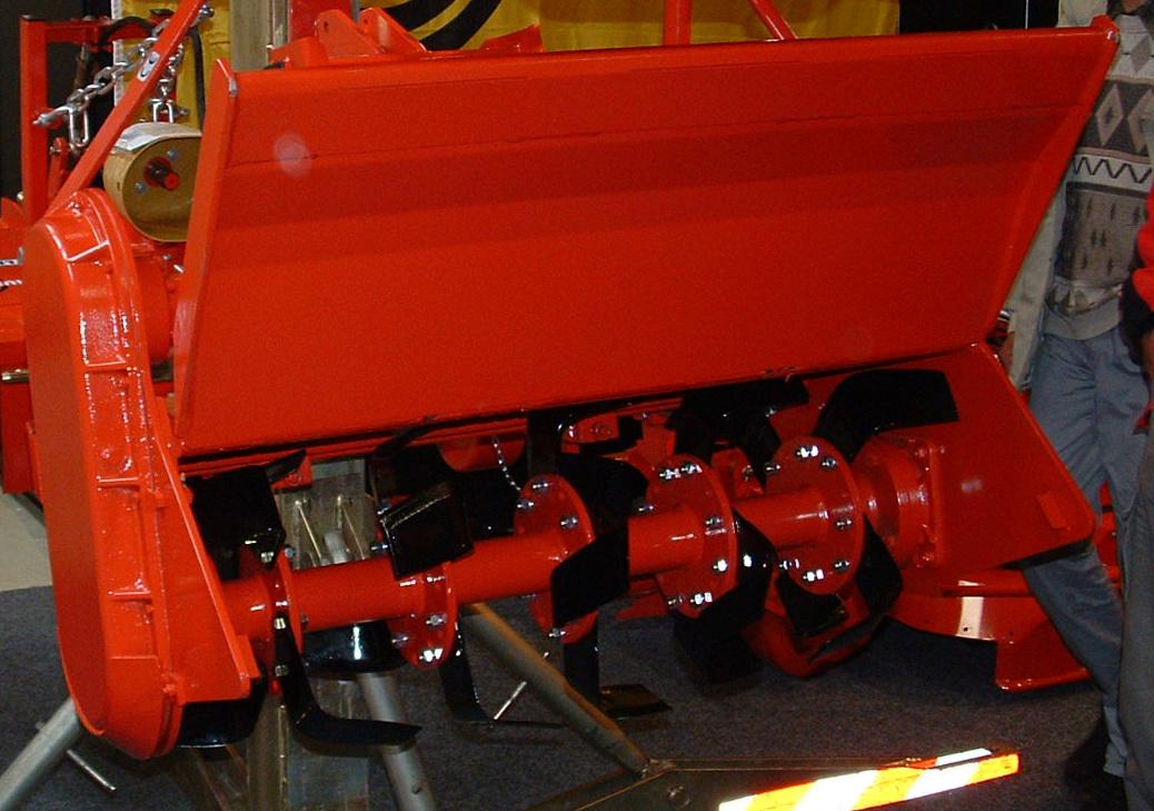
Figure 2.29 Rotary cultivator
During soil protecting work, another important influencing factor is the position of the adjustable cover plate placed behind the rotary cultivator’s axle. If set high it leaves a very lumpy soil surface. If the gap between the soil and the cover plate is narrow chopping will be more intensive and the soil surface will be smoother.
On compact soil, knives bent at a right angle are preferred to the bent knives cutting narrowly. Working depth must be alternated as well. It is recommended that a cultivator is used before the soil miller, since it facilitates the rotary cultivator’s penetration, decreases the wear of the equipment, and contributes to the breaking up of more compact soil.
Rotary harrows with an appropriate rotor rpm may be used for weeding, incorporating fertilizers, breaking up grass surfaces, or, at a greater travel speed, for limiting the cover vegetation’s growth. They are, however, not suitable for incorporating plant material into deeper soil (Figure 2.30). Compared to the rotary cultivators, their advantages are that the elements rotating opposite to each other do not compact the soil under the surface, and the risk of the equipment clogging up is also smaller, because of their self-cleaning capability.
Rotary harrows are sensitive to stones, therefore, to avoid overcharge, they are supplied with a sliding safety clutch and a trimming bolt fixed at the connection to the transmission shaft. These cultivating machines are stabilized with a spring to allow shifting sideways in order to avoid damage caused by stuck stones.
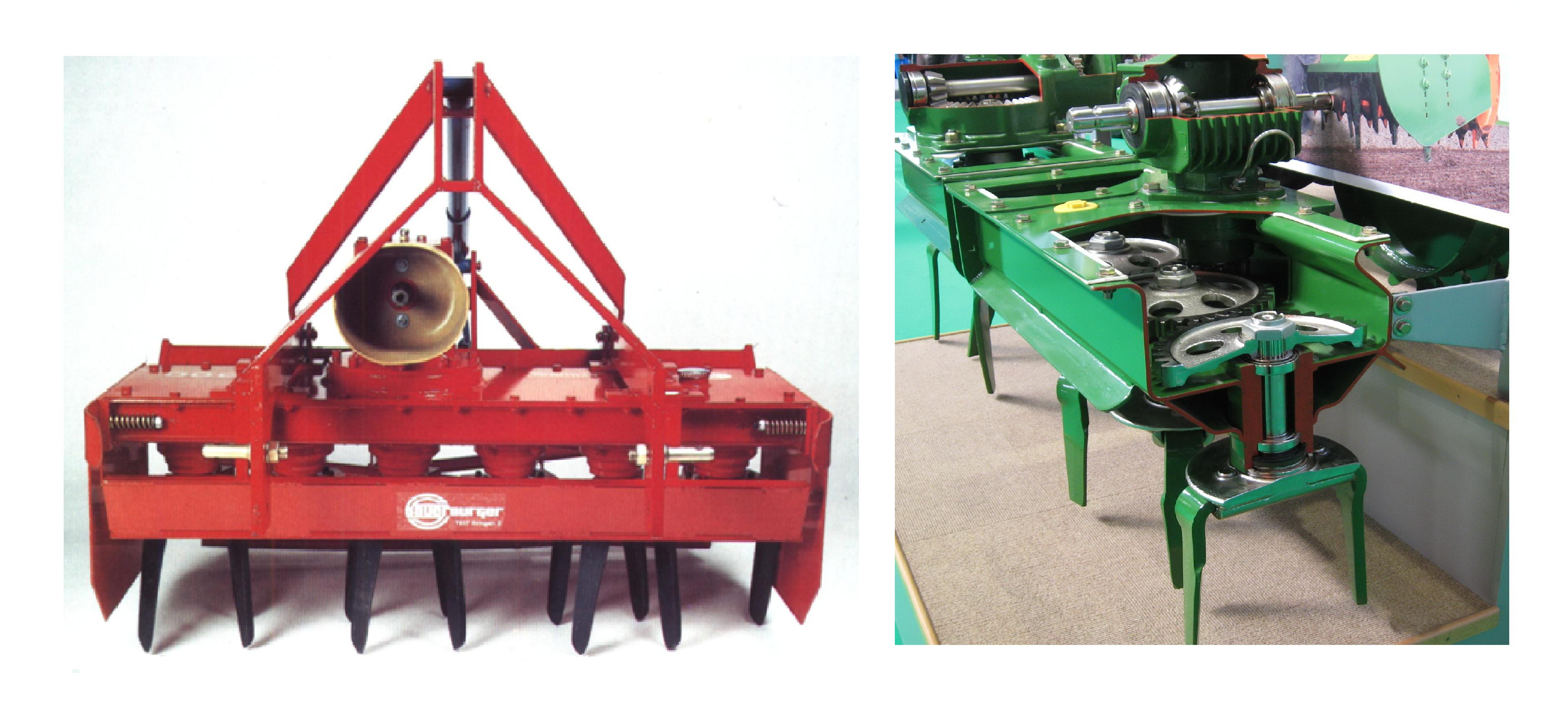
Figure 2.30 Rotary harrows
Machines in deep cultivation
Deep cultivation done before planting of the plantations, called deep plowing or deep turning is essential even today. According to the principle of loosening, there are two categories of deep-cultivating subsoil loosening equipment. There are tools for loosening by
-
lifting the soil, and
-
crumbling the soil layer.
The soil lifting equipment lifts the soil only vertically so that, although the soil crumbles, the soil layers do not get mixed. The subsoil must be sufficiently dry for effective loosening. This equipment comes in two versions, one with a rigid and the other with a flexible shank.
Subsoil loosening machines with a rigid shank are simple; their operation does not cause too many problems. Their sharp loosening knives break up the soil.
The tools of heavy and mid-deep loosening cultivators consist of a vertically positioned knife shank made of flat steel, at the bottom end of which one may find a chisel shaped loosening element set mostly slantwise. This breaks and loosens the soil in an upward direction. The efficiency of soil loosening depends on the number of the tools used and the runs made on the cultivated area. The loosening depth depends on the soil’s condition and the towing power of the tractor. Its usual depth is 30 – 40cm.
Their advantages are that machines have to be used fewer and their operation is simple. Their disadvantages are, however, that the loosening track-furrow is narrow, the loosening effect is minimal, and the towing power requirement is great.
Cultivators equipped with curved knives (Figure 2.31) are also called deep loosening or subsoil loosening cultivators. Their 70cm long loosening knife bent in a curve loosens the layer effectively up to a depth of 55cm. The subsoil loosening cultivator can be used for several purposes depending on whether the loosening knives are placed beside or behind each other. They may be used in cultures with or without cover vegetation to loosen tractor tracts or inter-row soil. Their advantages are several. Their retracting capability is good even on hard soil and they may be used for a variety of purposes. In addition, it is the only machine capable of loosening the subsoil of grassed plantations, it loosens the soil well and effectively, and, together with loosening the subsoil, it can perform drainage work as well. It is robust, blunts less, and it may be used also on wet soil. Its downside is that its towing power requirement is significant (15kW/loosening knife). (Walg 2005)
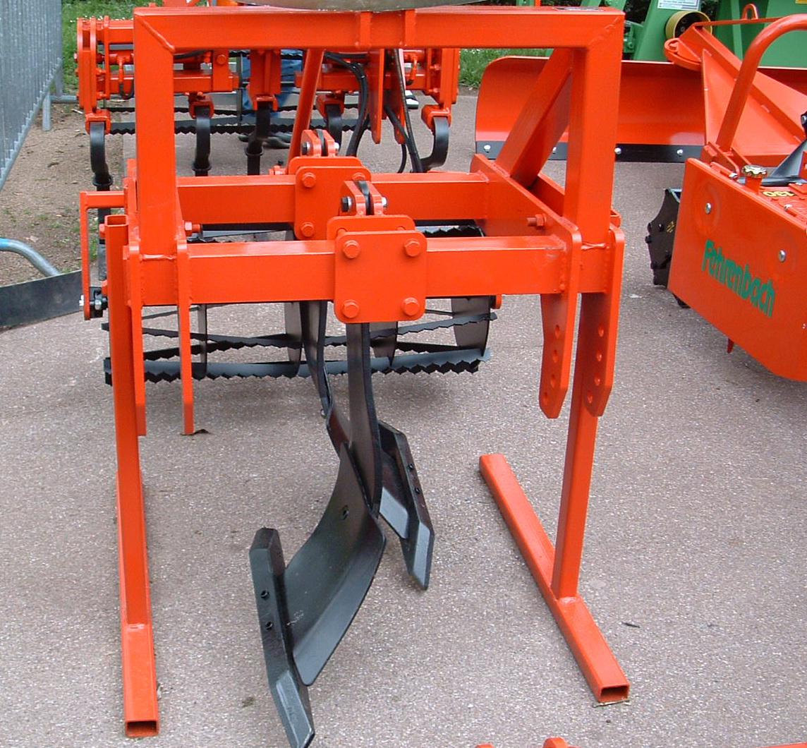
Figure 2.31 Mid-deep loosening cultivator with curved knives
Vibrating subsoil loosening cultivators
The loosening knives of these machines are driven via the power axle while the cultivating tools loosen the soil effectively without mixing the soil layers. Their travel speed is slower than that of the loosening machines equipped with rigid knives. Versions with lifting knives or swinging knives are known. Figure 2.32 illustrates their operational principles.
Loosening machines with lifting knives have a steel knife shank. However, the cultivating body driven via the PTO is mounted on the knife shank hinged with the bottom and can be moved up and down. Deep loosening machines with lifting knives usually have only one cultivating body, but they also have versions with two loosening elements. Their work depth is 45 -60cm.
Their advantages are that they penetrate hard soil well and their loosening efficiency is significant. Their disadvantages are that they are technologically more complicated than the loosening machines with rigid knives, their travel speed is slower, and their towing power requirement is greater.
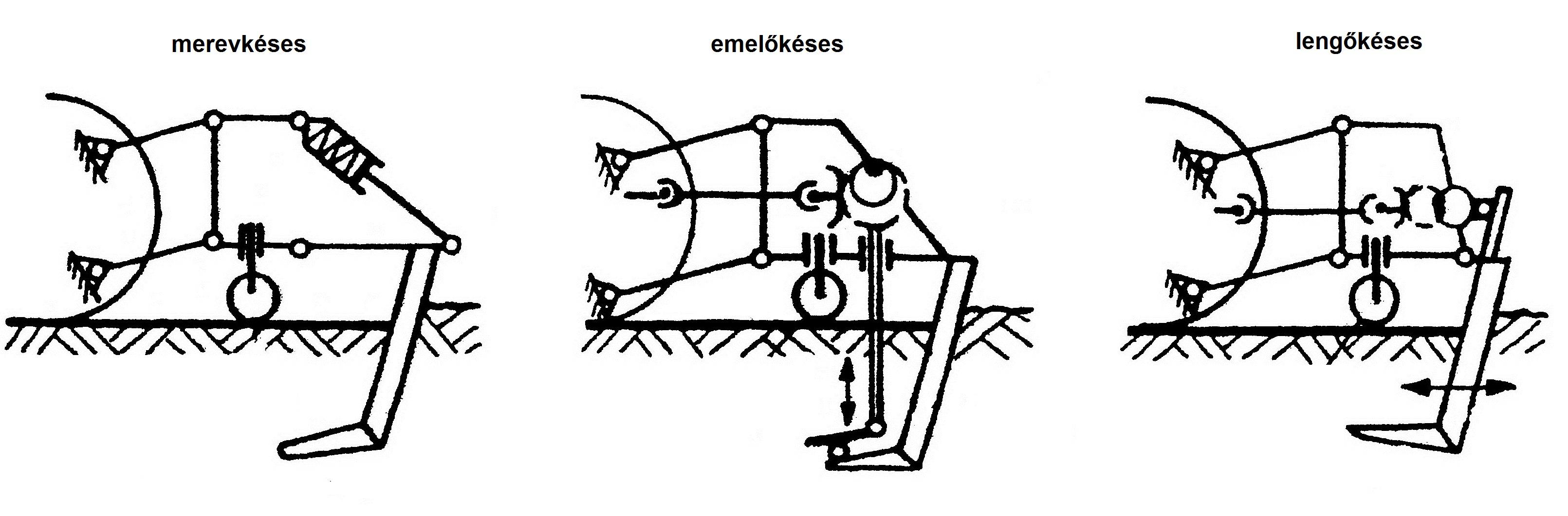
Figure 2.32 Operational principle of subsoil loosening machines
The cultivating body and the vertical steel knife shank of loosening machines with swinging knives are connected. With drive transferred via the PTO, the entire equipment swings periodically forward and backward on a vertical plane parallel with the travel direction. The machine is usually equipped with two cultivating tools. Their working depth is 40 – 50cm. Their advantage is the small towing power requirement. Their disadvantages are that they penetrate harder soil only with difficulty, and the vibration stresses both the tractor and its driver. (Moser 1984)
When loosening is performed by crumbling the soil layer, soil compaction is avoided not by lifting the soil layers, but by breaking them up.
Rigol plow
Traditionally, rigol plows (Figure 2.33) perform deep turning before planting, cultivating the soil 50- 90cm deep. As a result of the significant working depth, the furrow slice cannot be turned over completely. This procedure is applied less and less, because it results in the soil’s significant rearrangement and a lumpy surface. There are several downsides to this approach, namely that the valuable top soil is inverted, plow-shoe disease may develop, lumpy soil surface is left behind, and the furrows must be leveled.
In modern cultivation, deep plow turns the valuable top soil and subsoil loosening machines loosen the lower layers.
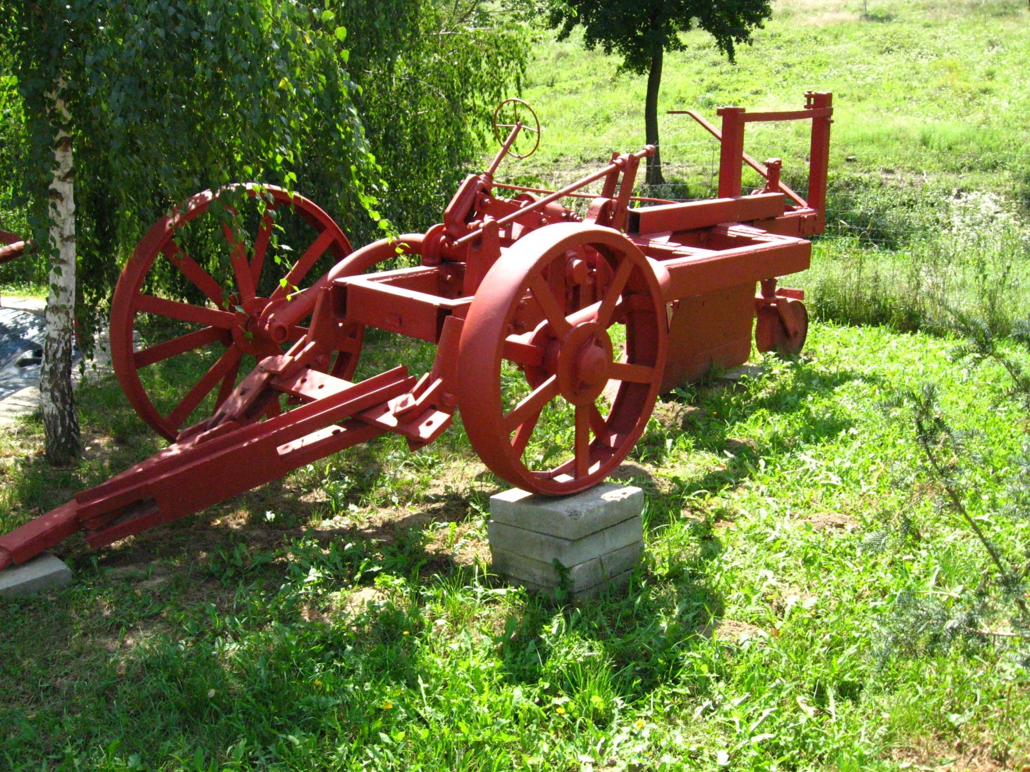
Figure 2.33 Rigol plow
Spade type cultivators
Spade type cultivators are the rotary and swinging type spading machines (Figure 2.34) They are driven via PTO. Larger spade equipment is used for the deep loosening of the soil before new planting or re-planting. They loosen the soil effectively and evenly in a depth between 40 and 60cm. When cultivation is completed, the area is relatively flat. Consequently, only a small amount of finishing work is necessary. Their work speed is slow, however. They do not cultivate the entire area, but only every second row.
The rotating spading machine turns the soil with a low rpm and re-works it 30-35cm deep. The cultivating body of it consists of spade shovels which are mounted helically on curved beams fixed to the axle rotating on a horizontal plane. As opposed to the swinging type machines, because of their rotating tool, rotating spading machine move much more steadily, and put much less stress on the tractor and its driver. Mostly, it turns, but also chops the soil. On pebbly soil, the rotating spading machine is of limited use.
The equipment’s advantages are that it loosens the soil effectively and evenly, and after its work has been completed, the planting machines have an easier job. Its disadvantages are several. First, the risk is great that the sole layer becomes compacted. In addition, as a result of having chopped untouched soil, new compaction may occur quickly, and on pebbly soil, the equipment blunts to a greater degree.
The cultivating tools of the swinging type digging machines (Figure 2.34) move on an elliptical path. The machines are equipped with four to six spade shovels which pierce the soil at an adjustable depth, lifting the soil and then dropping it down in lumps. These machines perform a great amount of turning work. Furthermore, they effectively loosen and aerate the soil, while gently chop the soil parts. As a result of piercing, the soil parts split apart on the bottom avoiding soil compaction. Because of its operational principle, the machine vibrates strongly, especially on dry soil.
Their advantages are that they do not burden the soil, perform satisfactory work also on wet soil, the risk of compact, hard soil is small, and they loosen the soil safely.
Their downside is that they do not always incorporate the remaining plants fully and the vibration stresses the tractor and its driver.
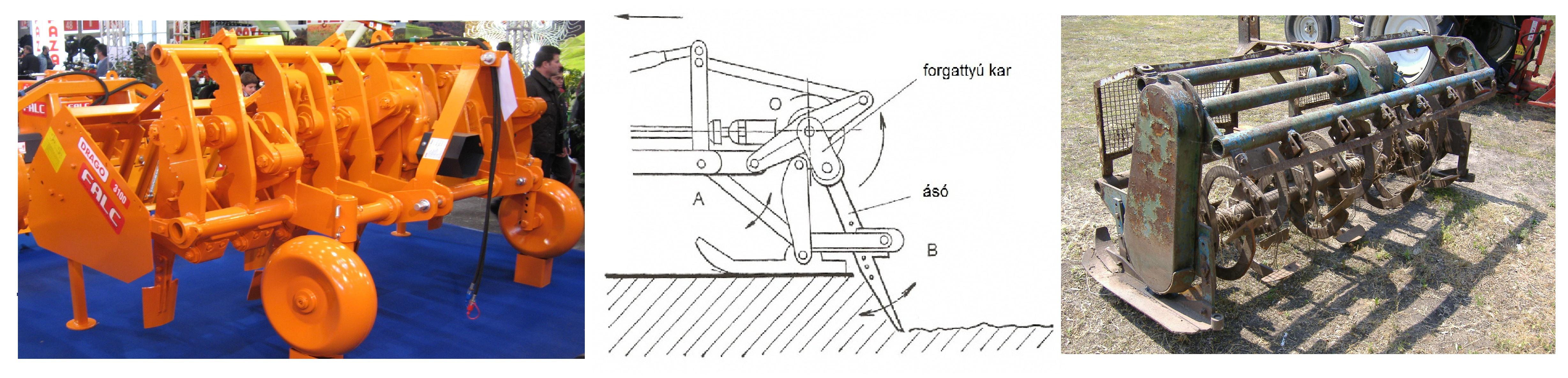
Figure 2.34 Piercing style digging machine and spade miller
Covering soil cultivation
Soil covering is the most environmentally friendly cultivation form; this meets best the basic requirements of cultivating plantation. In the course of performing covering soil cultivation, a portion of or the entire soil of the plantation is covered with plants or various covering material for a longer time period. This type of cultivation includes grassing of inter-rows, producing green fertilizer crops, covering tree strips with cover crops, and covering with various plant material or black plastic. With the exception of green fertilization, all other soil treatment methods meet the requirements of minimum tillage cultivation. Earlier, the grassing and the green fertilizing cultivation methods used on plantations were also called biological soil treatment. (Soltész 1997)
Grassing
Grassing is one of the most natural and beneficial soil treatment procedures. Grassing inter-rows may be possible by broadcasting seed mixture, autumn sowing, the maintenance of the natural vegetation indigenous to the location, or weed regulation.
Under the Hungarian climatic conditions, the grassing of inter-rows may be carried out safely only together with irrigation. In order to decrease water demand, often only every second inter-row is grassed.
Treatment of grass surfaces
On plantations with cover crops, the main task is mulching. Mulching is done primarily to decrease the water consumption of the cover crops. Their growth must also be limited and regulated in order to avoid disease and frost problems and to perform the various production procedures and tasks without complications. Depending on the location, precipitation, and the composition of the plants, mulching must be done 3-7 times a year.
The cutting height, depending on the composition of the plants, is 3-7cm. In addition to the appropriate cutting speed (m/s) of the machines, one must ensure that the tools are well sharpened and that the cutting knives blunt slowly. Two types of mulchers are used for mulching cover crops, one with horizontal axle, the other with vertical axle.
Mulchers with horizontal axle
In addition to mulching temporarily or permanently planted cover crops, these tools are suitable also for crushing wine shoots. As a result of their robust structure, mulchers with horizontal axle are also used to carry out tasks in forestry and residential land-scaping (land-scape protection).
The operational principle of mulchers with horizontal axle is similar to that of the rotary cultivator (Figure 2.35). The hinged knives are rotating with a high rpm vertically around a horizontal axle fitted with bearings. This solution makes the machine to be somewhat insensitive to stones. Depending on their design, there are universal (hammer and tine) knives, and cutting knives (bent at a right angle, Y and shovel shaped).
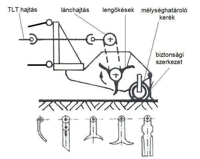
Figure 2.35 Mulcher with horizontal axle
The universal knives are blunt, and they break and chop, rather than cut. These knives are suitable mainly for chopping green fertilizers and vine. They are less appropriate for mulching cover crops, because they damage the grass surface.
As the knives have a small diameter circular track, the cutting speed at 1,500 rpm is only 30-40m/s. In order to achieve the appropriate cutting quality, these machines cannot work with the same travel speed as the mulchers with rotating knives. The cutting height may be changed between 2 and 5cm by adjusting the angle of the knives (the angle of the Y shaped knives to 120–140º). With greater bending (knives bent at a right angle), although cutting will be more even, the knives will not be self-cleaning anymore. In addition to the Y shaped knives, especially the shovel shaped knives have lived up to expectations in practice.
The concave shape facilitates sucking, thus, even in the tractor’s tracks, mulching is of a good quality, and a good crushing result may be achieved.
When using mulchers with swinging knives, the mulched material is spread evenly on the entire work area. The cutting depth may be adjusted vertically by depth limiting wheels or drums. The knife-axle is driven via V shaped belts located on the sides or via the gear box. Consequently, the working width is somewhat narrower than the entire width of the machine. The axle’s rpm is 1,500-2,500, which corresponds to a cutting speed of 30-60m/s. (Walg 2005)
Mulchers with vertical axle
Mulchers with vertical axle (Figure 2.36) leave a clean cutting surface resulting from their rather high work speed; consequently, they are especially suitable for mulching cultures with permanently planted cover crops. Their rmp is about 1,000, and their cutting speed is 60-100m/s. If cutting knive is appropriately sharp, their travel speed may reach even 10km/h. They maintain the determined cutting height relatively evenly. Their operation may occasionally cause problems, as they blow out the cut-off parings unevenly. Machines equipped with an uneven number of knives (for example, 1, 3) spread the mulched material always unevenly, while mulchers supplied with an even number of knives hardly ever do this.
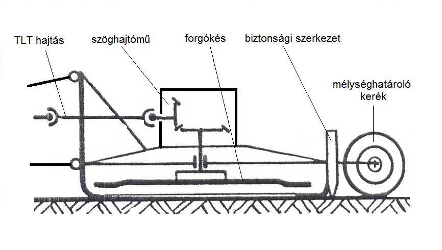
Figure 2.36 Mulcher with rotating knives
In case of mulchers with vertical axle, one or two knives rotate on a horizontal plane around its or their own vertical axle(s). They operate on the same principle as rotating mowerses. Depending on their construction, the knives are mounted securely on the driving gear or are rotated via V-shaped belts. In case of directly driven knives, with the exception of machines with an adjustable working width, the knives are rotating on the same plane at the same height. The knives are fixed mostly hinged, facilitating easier obstacle avoidance. The cutting height is usually adjusted by sliding skids or depth limiting wheels.
Swinging arm mulchers with rotating knives (row-bottom mulchers)
These mulchers, with the help of a swinging arm, enable the adjustment of the working width and the cultivation of the bottom of the rows (Figure 2.37). Shoots and plant remainders are left only close to the trunk. They can be removed only by spot spraying or trunk cleaners.
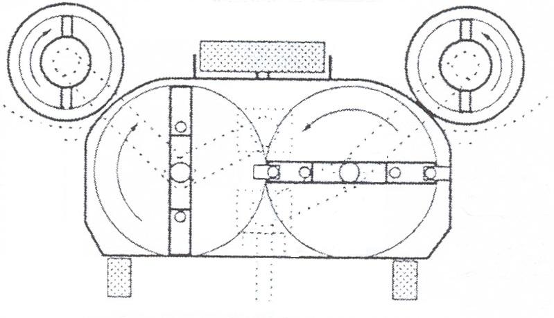
Figure 2.37 The structure of the swinging arm mulcher
The mulcher cultivating the bottom of the rows on a work width of 1.10 – 1.4m is a machine equipped with two rotating knives. Usually, a mulching plate with a knife is attached in the back to each side of the machine. The task of the shock absorber plate is to lead the swinging discs evenly above the soil so that they do not contact. On most designs, the drive from the PTO is delivered to the mulching knife via the gear box with the help of V belts.
Depending on their type, mulchers with rotating knives may be equipped with mechanical or hydraulic sensors.. In case of mechanical sensors, when prompted by the resistance of an obstacle, the swinging arm bends back against a spring. Therefore, rubber or plastic ledges are used to absorb shock between the trunk and the arm.
The disadvantages of mulchers with swinging arms are that they often break down and their travel speed is slow, 3 – 3.5 km/h. In most plants, they cultivate the bottom of the rows mechanically or spray it with herbicides. (Walg 2005)
Machines in row-bottom cultivation
In viticulture practice, the term “row-bottom cultivation” means the tasks performed on the soil beneath the foliage. Several procedures are known. The following table summarizes the various possibilities.
Row-bottom procedures |
||
|
mechanical |
soil covering |
chemical |
|
one-sided cultivator knife cultivating plow trunk cleaner driven harrow mulcher |
grass parings straw tree bark |
strip spraying ULV spraying spot spraying |
Mechanical row-bottom cultivation
Among the mechanical machines, there are tools which are suitable for open row-bottom cultivation, and row-bottom mulching tools which are also suitable for row-bottom cultivation provided the surface is fully covered with cover crops.
In most cases, the row-bottom cultivating machines are positioned at a right angle to the travel direction. They must be capable of avoiding obstacles in their way, such as wine-stocks and posts. The machine’s maneuvering movement is guided by the shifting of a sensor placed in front of the equipment, which, upon touching obstacles (trunks, posts), bends back. Spring pressure prompts the sensor, after the machine has completed the maneuver, to return to the original position.
In practice, mainly two solutions are used. In the first case, when the sensor shifts, the cultivating equipment bends back and avoids the obstacle. In the second case, it retreats from the obstacle perpendicularly to the row, and, after having left the obstacle, it turns back to the direction of the row.
The sensor’s movement steers a dual-action hydraulic work cylinder with a hydraulic valve, moving the equipment forward and backward with a small time-lag so that, at the time of avoiding an obstacle (wine-stock), it follows exactly the sensor’s movement. (Figure 2.38)
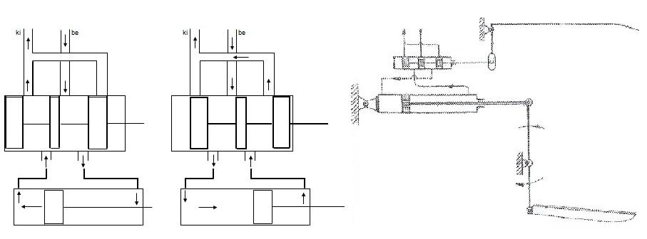
Figure 2.38 Maneuvering hoe
Mainly the so-called displacement-regulating system is used as opposed to the stroke-regulating system (pulling back the tool completely, along the entire length of the stroke). The advantage of the displacement-regulating system is that the safety distance on the sides between the tool and the stock is always the same at the time of making the maneuvering movement. The tool moves as much as required by the position of the obstacle. As a result, uncultivated areas, except for the safety strip, are smaller than in case of the stroke-regulating system.
Figure 2.39 provides an example of the stroke-regulating system. The active cultivating equipment, which is a rotary cultivator on the Figure, is mounted on a hinged parallelogram frame. The PTO drives the hydraulic pump operating the system. The rotary cultivator is driven by the gear box which is driven via the PTO with the assistance of the transmission shaft. A dual-action hydraulic cylinder adjusts the diagonal of the parallelogram enabling the cultivator to shift parallel with itself. Steering is done by a hydro-electronic system.
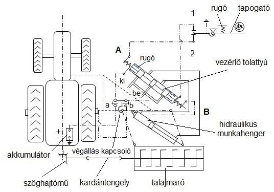
Figure 2.39 The steering of a detouring row-bottom cultivating tool
The steering unit receives electric current from the battery in the following manner. The negative pole is attached to the tractor’s structure (body), while the positive pole closes via the steering piston’s retracting A and B reels and the a and b disconnecting relays through the sensorr’s contact, since the sensor is also earthed. On Figure 2.39 the so-called swimming position can be observed. In this position, as the sensor does not touch the obstacle, when prompted by the pulling spring, it touches instead contact number 2. At this moment, reel A receives electric current, causing the piston to move upwards. The incoming oil going through the space between the middle and lower pistons flows into the work cylinder through its upper connection. As a result, the cultivator moves to the right in the direction of the row. After having completed a certain distance, the stop switch moving together with the cultivator’s frame turns off relay a terminating the supply of electric current to reel A. At this moment, the pistons of the steering piston prompted by the springs built into the house move into the middle position and the oil flow of the hydraulics stops. When the sensor reaches an obstacle, it switches on contact number 1 by shifting, and reel B will receive electric current. At this time, as a result of the steering piston’s shifting, oil flows into the cylinder from below and pulls out the cultivator perpendicularly to the row. This remains the situation until the stop switch turns off relay b terminating electric current to reel B.
A tractor with 15-20kW is necessary for its operation and its working speed is 2-4km/h.
The maneuvering equipment facilitating the avoidance of obstacles may be placed in front of the front wheel of the tractor, between the front and rear axles, or in the back. In practice, front suspension is rarely used. This approach may become necessary only where “under-belly” suspension (that is under the tractor’s belly) is not possible, for example, in case of caterpillar tractors or engines with a narrow gauge or body steering.
Oversteering (the degree of shifting resulting from steering) is the biggest downside of the front suspension. In addition, the front lifting-suspending equipment is more costly in terms of material and other expenses.
Mounting between the axles is advantageous, because the rear suspension structure remains free for other tools.
In case of rear suspension, the tools are mounted on a 3-point hitch gear attached to the frame, or on other work equipment. In this case, their connection is simple, but the driver does not see the work equipment. Consequently, driving, while paying attention to the rows, is hardly possible.
Plow body
Among the row-bottom cultivation procedures, the oldest mechanical task is clearing and opening the rows with a plow body. This procedure is used less often today, because it must be supplemented by manual hoeing.
Row opening should be done late spring to put the emerging or still sprouting weeds into the inter-rows. After opening, inter-rows must be leveled again to facilitate the movement of the machines doing plant protecting and green work. Opening is performed by plow bottoms. In their structure, these look only similar to the traditional plows, as in this case, the plough-share is rounded and the steering plate is set steeper. In addition, there is no plough-reed or sliding skid on them, since their driving is assisted mainly by the suspension gear. The opening plow bottoms are often equipped with detouring cultivator bodies supplied with sensors (one-sided hoe) to avoid the necessity of too much finishing work.
One-sided cultivators (spoon shaped hoes)
The most widely used row-bottom cultivating tool on plantations with open cultivation is the one-sided Dutch hoe (Figure 2.40). As opposed to plow bodies, their advantage is that, instead of removing the soil, they only loosen it, and, at the same time, cut the weed roots. The one-sided hoe is a straight knife, fixed to a vertical axle, to enable the hoe to turn into the row. The knife bends slightly downwards, with a spoon shaped hollow at its end. This shape gave its name: spoon hoe.
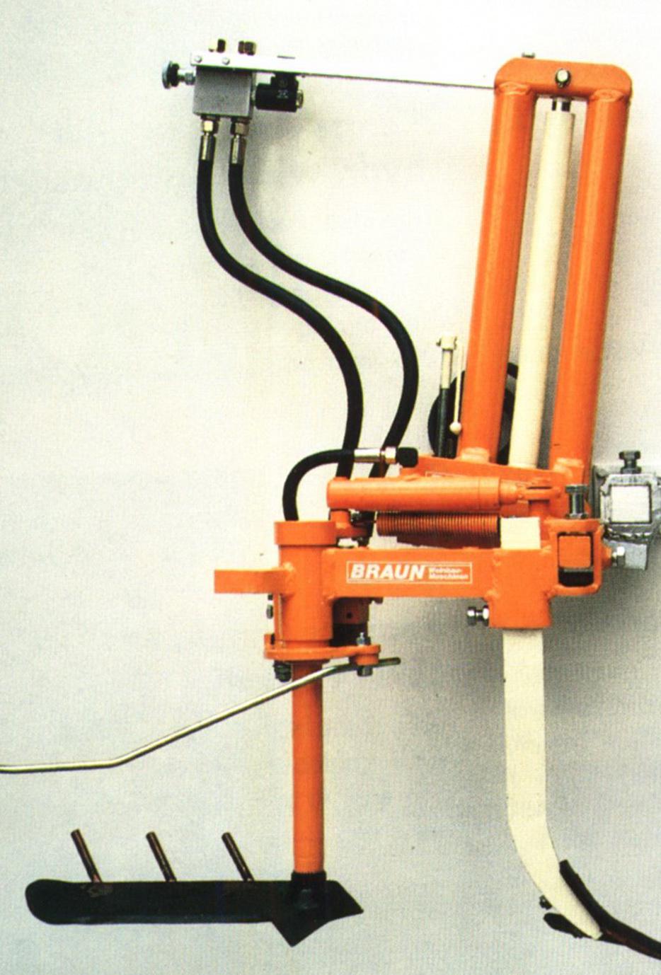
Figure 2.40 One-sided Dutch hoe
Spring force pushes this cultivating tool into the soil. As the tractor proceeds, it cultivates in a shallow depth of 5-8cm under the soil surface. The working depth of the one-sided hoe may be adjusted by using depth limiting wheels, or by depth maintenance depending on other (for example, roller harrow) equipment. On plantations with cover crops, disc leaves or disc coulters roll in front of the one-sided hoe to separate the cultivated area from the uncultivated areas with inter-row cover crops. The cultivating speed of the one-sided hoe is 4-5 km/h.
Steering without contact
For the purposes of steering without contact, ultra-sound sensors are used. Ultra-sound is issued by its transmitter. The receiver senses the ultra-sound reflected by the obstacle. The sensor starts to operate upon receipt of the reflected waves, causing the cultivating tool to bend backwards from its original position. As soon as it has left the obstacle and the receiver does not sense reflected waves anymore, the tool returns to its original position. Today, this procedure is rarely used yet in practice.
Row-bottom mulchers
We have already discussed mulchers with swinging arms as the tools of inter-row and row-bottom cultivation. In addition to these, however, there are tools with rotating knives designed for mulching. Most often, these can be located “under-belly”, mounted on the axle of the row-bottom cultivating tools.
Trunk cleaners
Trunk cleaners are primarily used for the removal of water sprouts and extensions. Consequently, these tools may be used also for weeding the bottom of the rows. Their work quality is rather good on areas sowed with biennial green plants. On grassed areas, quality is good only if the grass has grown and the lawn has received sufficient precipitation becoming green again within a few days. We will discuss their structure and operation when we talk about machines used in green work.
Chemical row-bottom cultivation
In the last two or three decades, chemical weeding was not carried out on the entire area of the plantation. Combining with mechanical cultivation of inter-rows or their grassing, chemical weeding is done in orchards, but only on 60-150cm wide tree strips, and in vineyards only in the bottom of the rows.
Depending on the distribution method of herbicides, the following procedures are known.
|
Spraying |
ULV pulverizing |
Coating |
Drop spreading |
|
Backpack sprayer Tractor-mounted sprayer (strip spraying) Hose spraying Spot spraying Strip spraying with optical chlorophyll identifier |
Manual tools Tractor-mounted air-assisted atomizers |
Manual tools Tractor-mounted tools |
Manual |
Currently, the drop spreading procedure has no significance in wine growing, and the coating procedure is also only rarely used. This is an efficient procedure, especially on sloping areas, as an alternative to the procedures of soil cultivation machines increasing erosion risk.
Backpack sprayers
These are still often used on young plantations, and on sloping areas cultivated with winch-powered equipment. There are piston backpack sprayers (manually operated backpack pump sprayers), high-pressure backpack sprayers, and motorized backpack sprayers.
In case of piston backpack sprayers, pumps are responsible for creating the necessary pressure. Pressure volatility in the pump is balanced by an air boiler. Although these machines may be operated cheaply, their disadvantage is that the spraying pressure is volatile, forming uneven droplets.
The tank of the high-pressure backpack sprayers is filled not more than up to two-thirds of the tank. In the remaining space, a manually operated air pump compresses the air above the spray. During treatment, the original pressure continuously decreases, thus, the amount of the distributed spray and the size of the droplets change to a great extent.
Motorized backpack sprayers are driven by a two-stroke engine. They belong to the air-assisted atomizer plant protecting machines. Centrifugal pumps facilitate the delivery of the spray to the nozzles. The pressure can be adjusted between 0.5 – 9 bar by the motor’s rpm and a pressure relief valve. Their disadvantage is that they are heavy and noisy during the motor’s operation. The manual spraying pipe (backpack sprayer, hose sprayer) connected to the hose can be recommended if it has a built-in manometer and an adjustable pressure regulating valve.
Tractor- mounted sprayers
For the purpose of strip spraying, the traditional tractor-mounted sprayers are equipped with a spraying pipe which is attached before the front axle of the tractor or in between the axles (Figure 2.41). It is advantageous, if the spray tank is positioned before the front axle and spray is distributed by an electrically driven pump, because then also a cultivator, a mulcher or other equipment can be mounted on the rear suspension gear. For the distribution of herbicides, also the tanks, pumps, or other feeding tools of the sprayers or pulverizers may be used.
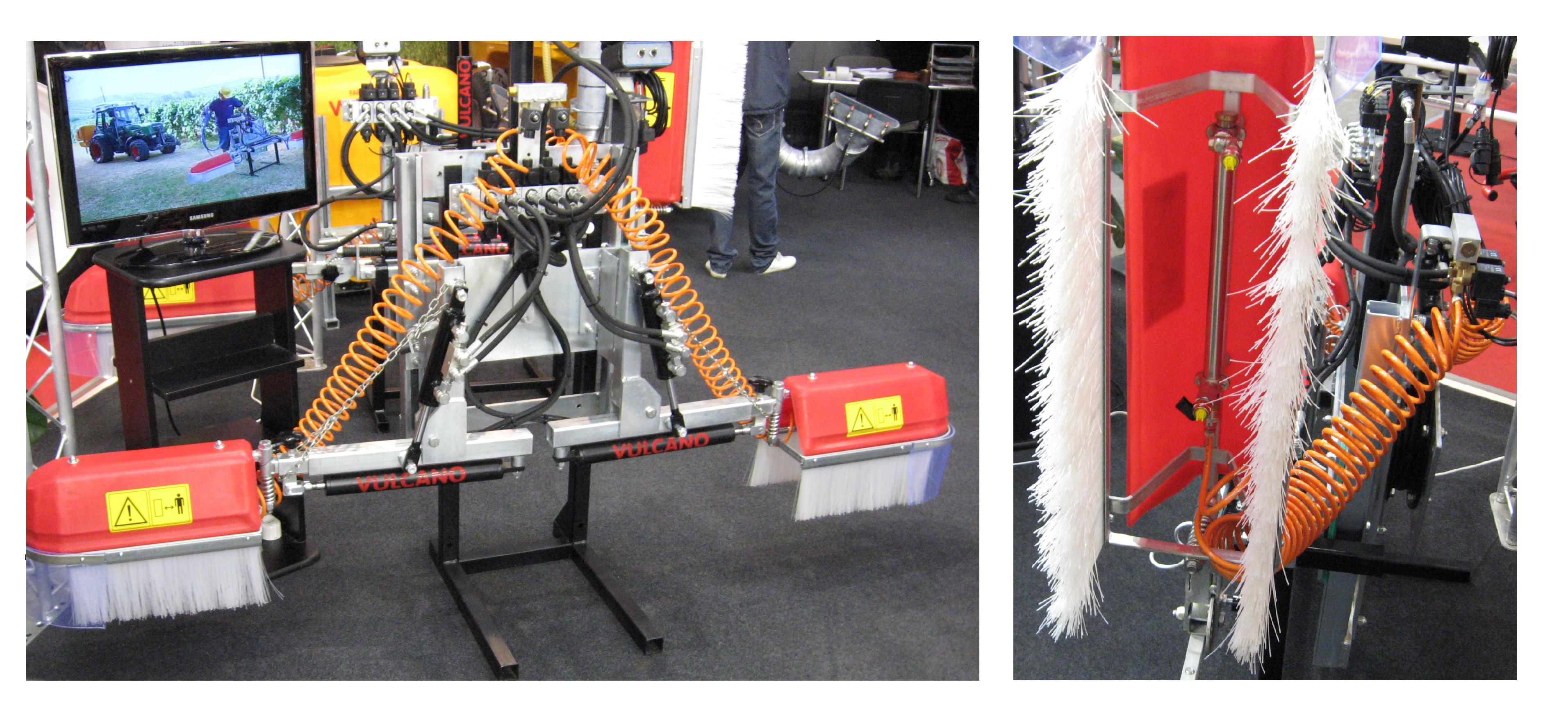
Figure 2.41 Strip-sprayers equipped with protective wrap
Spraying with a hose
On sloping areas where winch-powered cultivation is carried out, hoses equipped with spray guns may be attached to the sprayer. For direct towing, the sprayers can be transformed so that the two fittings closing down the sides and attached to the left and right of the spraying pipes are removed and, in their stead, hoses equipped with spray guns are attached.
Spot spraying
On plantations, the biggest herbicide savings may be achieved by utilizing spot sprayers. The use of the agent is limited to the weeds located around the plant and in the direction of the row. The most modern spot sprayers are supplied with optical sensors. An optical sensor can be easily fixed before the front axle of the tractor or between the axles or may be suspended in the back. The sensor senses the objects, for example, the posts or the wine-stocks with the help of the reflected light. Upon sensing an object, it gives a spraying impulse. A magnetic valve ensures the supply of the spray guns. The time period of the spraying impulse may be adjusted depending on the travel speed. Spray consumption is 15-20l per hectare, and agent consumption is 0.2-0.3l.
Stripe sprayer with an optical chlorophyll identifier
The stripe sprayer equipped with an optical chlorophyll identifier regulates the distribution of the spray optically, and sprays only where there is chlorophyll, that is weed. (Figure 2.42)
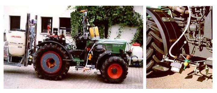
Figure 2.42 Stripe sprayer equipped with optical chlorophyll identifier
It follows the principle that the plant is green, and the reflected light behaves differently from when it is reflected by soil or other objects. If an optical sensor is gradually adjustable, the machine may leave behind a certain portion of the weed or performs full weeding. Similarly to the spot sprayers, a magnetic valve opens or closes the spray nozzles.
ULV air-assisted sprayers
ULV (Ultra Low Volume, meaning very small spray consumption) sprayers come in two versions (Figure 2.43), manual and mounted. A rotating, cone shaped pulverizer with a fluted rim ensures the precise distribution of the undiluted spray. The mechanical drop formation operates on the principle that when the spray (herbicide) flows onto the rotating pulverizer, it disintegrates into very small (30 micrometer) droplets as a result of the acceleration and centrifugal powers. Rotating pulverizers are driven by electric (accumulator or battery) motors with 4,500-5,500 rpm.
The advantage of this procedure is that, as the equipment is light, it may be held in the hand. Its disadvantage is, however, that the user has hardly any possibility to monitor performance during work, as the drops are so small that they are hardly visible.
The rotating pulverizing head is surrounded by a protective wrap which, when meeting an obstacle, is squeezed together by spring power. This facilitates moving directly also along the wine-stocks and posts. Herbicide is sprayed to the bottom of the row through the side opening of the protective wrap. (Walg 2005)
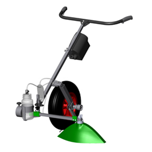
Figure 2.43 Manual ULV strip sprayer
Machines in planting of plantation
Tools for establishing new plantations
Before establishing new plantations, the following preparatory steps are taken:
-
measurement of the uncultivated areas,
-
soil analysis for the determination of the basic manure,
-
deep turning, and
-
designation of rows.
After having completed these steps, planting may begin.
Planting methods
Manual and mechanical planting methods may be used in the planting of rooted wine grafts. Manual planting procedures are applied in areas which tractors cannot approach, on smaller plots for stock replacement purposes, and on soil not suitable for mechanical planting.
For manual planting, hoes, clawed or gouge planting drills, trowels and planting iron equipped with handles may be used.
Soil drills may be classified as follows: spiral conveyer (lifting earth) drills and compacting drills. For preparing planting pits, the spiral conveyer drill may be preferred, because compacting drills compact the wall of the hole too much.
The manual drills are operated by two people. The diameter of the bore depends on the variety of drill diameter (approximately 10-20cm). The soil drill cannot be operated on pebbly soil. Since working with manual drills is exhausting, it is better to use a tractor-mounted drill driven via the PTO. With this equipment, several bores may be drilled simultaneously. Hydraulic soil drills are easily manageable. They are mounted on a swinging frame and may be steered even from the cab of the tractor.
Hydro drills (Figure 2.44) ensure fast and simple planting, and have a relatively big area capacity. Through a nozzle placed at the end of the hydro drill, water pressed out with a 2-4 bar pressure rinses the earth out from the bores. Hydro drills are attached via a hose to a container supplied with a pump (for example, plant protecting machine filled with water). Depending on soil conditions, each bore requires 1.5 – 4 l water. Not all soil is suitable for the use of hydro drills.
They are also suitable for preparing the bores of the posts before planting.
Mechanical planting
The soil surface must be levelled before using the planting machines, as tractor tracks must be removed from where the rows are to be planted. The location of the grape-vine must also be marked. Laser-steered planting machines ar also in use today.
The vine planting machines (Figure 2.45) are special tools which combine the various elements of planting rooted grafts. In case of mechanical planting, the tasks related to preparing the planting ditch, depositing the vine grafts into the soil, filling up with soil, and compaction are performed in this order. As a filling tool, they use a disc leaf to be adjusted based on the current soil conditions. The rooted vine graft is placed into a rotating arm supplied with a handle. While the planting machine hauled by a tractor moves forward, planting occurs automatically in the furrow made by the opening unit. After deposit, the two compacting wheels push the soil to the vine grafts. In order to maintain an accurate depth, the planting machines are equipped with adjustable depth limiting wheels. One person performs the job in a comfortable sitting position. The distance between the plants may be changed up to about 1.5m. With the one-row planting machine, 800 - 1,200 vine grafts per hour can be planted. There are two-row planting machines with which it is possible to plant 4,000 plants per hour.
The accurate row marking and row orientation significantly influence work efficiency. Efficiency is achieved if the planting machine maintains the correct distance between the plants, the distance between the rows is constant, and the problem of leaving the rows by machines in a straight line is perfectly solved.
Modern machines are steered by visible laser beams made of helium. The laser is set up at the end of the plantation issuing beams toward the row. The receiver catches the beam and senses the deviation to the left or to the right of the beam. When this happens, it opens or closes the valves of the hydraulic steering electrically. The machine is mounted the 3-point hitch towing plate and is moved into the correct direction. The correction of the deviation is fast and accurate.
As a supplementary visual check, the driver of the tractor can observe the required correction with the help of three lamps (straight, to the right, to the left). The vine planting machines, if adjusted correctly, ensure the correct distance between the plants, the same planting depth, the correct deposition of the rooted grafts into the planting ditch or soil, the appropriate closure of the soil for the long roots, and the even positioning of the fine wine stock above the soil.
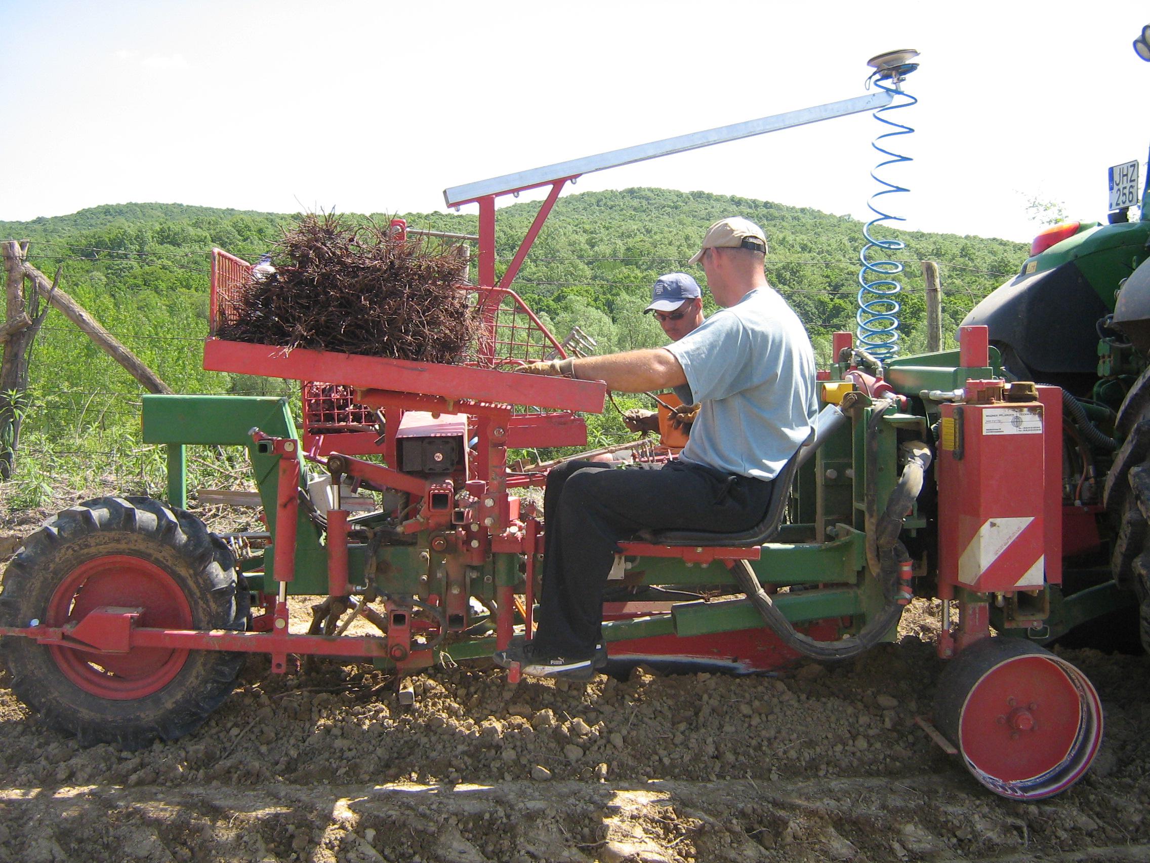
Figure 2.45 Planting machine
Control questions
1. Explain the term „land improvement” and discuss the related technical procedures and the machines used in performing these procedures!
2. Describe field clearing machines, their structural design and operating circumstances!
3. Summarize the theoretical issues arising in land scraping!
4. Provide a summary of machines used in landscaping and landshaping based on their structural design and operating principles!
5. What types of procedures are used in cultivating plantation and what types of soil cultivators are suitable for carrying out these procedures?
6. Characterize the machines used in inter-row cultivation and their operation based on their structural design and operating methods!
7. Describe the structural design and application of machines used in deep loosening work!
8. Discuss cultivators working on plantations with cover plants!
9. With the help of a drawing, present the various steering mechanisms of maneuvering or detouring machines designed for row-bottom cultivation!
10. Provide an overview of the mechanized row-bottom cultivation procedures using chemical agents!
Bibliography
|
Horváth B. szerk.: |
Erdészeti gépek |
|
Szaktudás Kiadó Ház Rt., Budapest 2003 418 p. |
|
|
Karai J. - Horváth Á.: |
Tájrendezõ és kertépítõ gépek |
|
Budapest 1992 197 p. (Egyetemi jegyzet) |
|
|
Moser, E.: |
Verfahrenstechnik Intensivkulturen |
|
Verlag Paul Parey, Hamburg und Berlin 1984 204 p. |
|
|
Soltész Miklós szerk.: |
Integrált gyümölcstermesztés Mezõgazda Kiadó |
|
Budapest 1997 842.p |
|
|
Szabó János szerk.: |
A melioráció kézikönyve |
|
Mezõgazdasági Kiadó Budapest 1977 |
|
|
Walg, O: |
A szõlõtermesztés géprendszere |
|
Mezõgazda Kiadó Budapest 2005 309 p. |
![]()
![]()

Hírek/News
Sajtóközlemény
A projekt célja magyar és angol nyelvű digitális tananyagok fejlesztése a Budapesti Corvinus Egyetem Kertészettudományi Karának hét tanszékén. Az összesen 14 tananyag (hét magyar, hét angol) a kertészmérnök Msc szak és a multiple degree képzés keretében kerül felhasználásra. A digitális tartalmak az Egyetem e-learning keretrendszerével kompatibilis formában készülnek el.
BővebbenSikeres pályázat
A projekt célja magyar és angol nyelvű digitális tananyagok fejlesztése a Budapesti Corvinus Egyetem Kertészettudományi Karának hét tanszékén. Az összesen 14 tananyag (hét magyar, hét angol) a kertészmérnök Msc szak és a multiple degree képzés keretében kerül felhasználásra. A digitális tartalmak az Egyetem e-learning keretrendszerével kompatibilis formában készülnek el.
A tananyagok az Új Széchenyi Terv Társadalmi Megújulás Operatív Program támogatásával készülnek.
TÁMOP-4.1.2.A/1-11/1-2011-0028
Félidő
A pályázat felidejére elkészültek a lektorált tananyagok, amelyek feltöltése folyamatban van.
![]() TÁMOP-4.1.2.A/1-11/1-2011-0028
TÁMOP-4.1.2.A/1-11/1-2011-0028