Vegetable harvesting technologies
8. Vegetable harvesting technologies
The cost of manual harvesting of vegetables accounts for up to 2/3 of the total production costs. Therefore, mechanization of harvesting plays an important role in the economy of production.
Analysing the process of manual harvesting, 3 phases can be distinguished: picking or detaching the harvested parts (fruits, buds, tubers, roots, leaves, etc.) of the plant, collecting them in buckets, sacks, crates, cases, containers or trailers, and finally transporting
the same to the collecting or processing location.
Depending on the level of mechanisation of the above 3 phases, 3 harvesting technologies are available: harvesting with tools, harvesting using mechanical aids, and fully mechanised harvesting.
Usually, fresh market products are harvested manually, to avoid damage caused by the harvesting machine.
The products harvested by machines are processed by the canning or refrigeration industry.
8.1 Harvesting using collecting tools
When using this technology work in all 3 phases is carried out manually. It is characterised by the use of collecting facilities.
Due to size unification most of the collecting facilities are offered in standardised sizes. By multiplying the smallest one we get to a larger standardised unit. The largest unit is the pallet which can be loaded by a forklift (Figure 8.1).
Fresh market vegetables are wrapped and packed immediately in the field in bins and trays which are placed on shelves of the stores. Some of the bins and trays are for one-time use only, others are reusable. These are generally made of plastic.
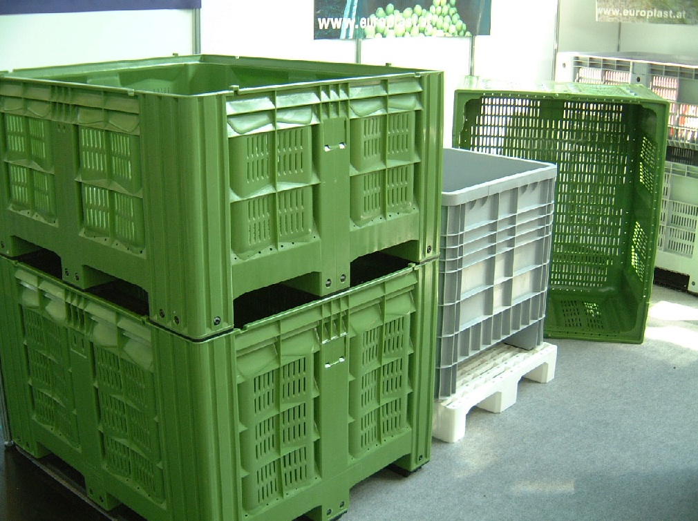
Figure 8.1 Plastic pallet bins
8.2 Harvesting with mechanical aids
With the use of harvesting aids the collection and/or transport of products is mechanised.
The mechanical aids are special vehicles which increase productivity by 20-50%.
In most of the cases the workers are walking behind the mechanical aid and put the detached vegetable on a belt or into a container (Figure 8.2).
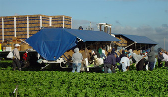
Figure 8.2 Mechanical aid in use. Pickers are collecting the harvested product directly in boxes
Some examples of mechanical aids are shown in Figure 8.3.
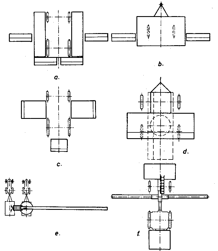
Figure 8.3 A few typical arrangements of mechanical aids
-
Tractor-mounted platforms for carrying buckets or cases
-
Tractor-towed platform for carrying buckets or cases
-
Tractor-mounted platforms for carrying pallet bins
-
Special trailer with turning platform for transporting and collecting hand-picked vegetable (platform in transversal position for collecting, in longitudinal position for
transporting purpose)
-
Tractor-towed collecting conveyor belt
-
Tractor-mounted conveyor belt
To make the work of hand pickers more comfortable, attempts were made to create a sitting or lying position on the machine.
Sitting proved to be less comfortable because of the stretched position of the legs.
Picking in a lying position is more advantageous. In the so-called 'cucumber aircraft', designed and constructed at the University of Hohenheim, pickers are harvesting pickling cucumbers in lying position.
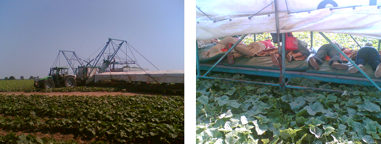
Figure 8.4 Cucumber harvesting aid in use
8.3 Fully mechanised vegetable harvesting
The special features of mechanised vegetable harvesting are as follows:
-
Almost each species needs a separate harvester type,
-
Special varieties are needed with high yield and high damage-resistance,
-
In most cases once over harvesting is carried out, which requires varieties with uniform ripening.
-
The machine-harvested product is mostly processed by the food industry,
-
The quality of machine-harvested product is generally lower and its yield is generally less than those harvested by hand, and
-
Selective harvesting is still in research status. One of the possible solutions seems to be the use of robots.
8.3.1 Mechanical harvesting of field tomatoes
R&D in the mechanisation of mechanical tomato harvesting started at the end of the 1950s at the University of California on the basis of potato harvesting. Since that time, the working principle of harvesting has not changed much. The necessary technological steps are:
-
The stems of the plants are cut under the soil surface,
-
A conveyor chain transports the bushes and the berries dropped earlier on the soil together with the cut soil layer to the shaker unit,
-
The shaker removes the berries from the plants and drops the bushes to the ground behind the machine,
-
A fan removes leaves and other impurities,
-
The berries are sorted according their colour, and
-
The red berries are collected in a transport vehicle.
Specialities of the tomato plantation
For mechanical harvesting special tomato varieties are needed. They have to bear firm berries to “survive” the mechanical impacts of the harvesting process without suffering any injury. The berries must ripen uniformly (they must be at least 80% red at the time of harvesting) to avoid unacceptably high losses. They must be of determined growth. Also high yield (min 45 t/ha) and dense leafage (to lessen the impact) is required.
Tomatoes can be grown on flat arable land or on ridges (in Hungary 1.6m wide). They are transplanted or sown in double rows (35cm), plant distance in the row is 20-35cm (Figure 8.5).
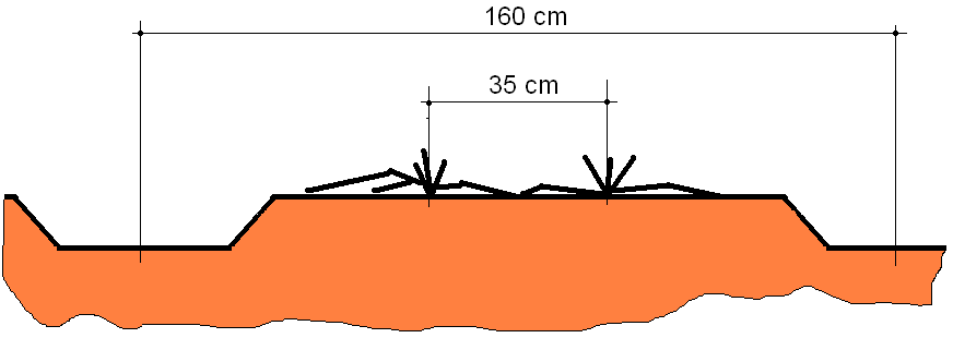
Figure 8.5 Tomato plant arrangement on the ridges
Main parts of the harvesting machines
In current practice, the harvesting machines cut off the plants, forward them to the shaker unit, detach the berries, remove the yellow and green tomatoes and clods, and forward the ripe exemplars into the collecting trailer.. In the following section we discuss the most typical solutions of these technical elemnts.
Cutting – forwarding unit
Their task is to cut off the plants underneath the soil surface and to forward them to the grid conveyor.
On the first harvesters, the applied rigid knives were fixed to the machine frame in a left-leaning position. These however were very sensitive to the strong, woody weed. That is the reason why today the knives are designed to be active and self cleaning. The most often used types are the cutter bar and the rotating disc units.
The cutter bar units consist of a series of edged blades similar to those on the combine harvesters. Curved forks are located above the blades to prevent the tomato berries from being cut.
As the blades run in the soil they wear out fast. They must be replaced 2-3 times in a harvesting season. When a cutter bar is used on the harvester, a rubber finger reel is needed to forward the plants on the sloped conveyor.
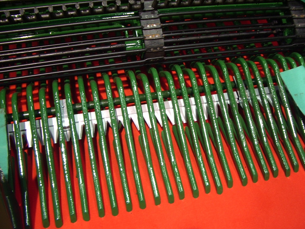
Figure 8.6 Cutter bar with curved forks
Figure 8.7 shows a rotating disc cutting-forwarding unit. The usual diameter of the sharpened edge discs are 90-100cm, their slope is 20-250 to the horizon. The front edge of the discs works 5-8cm deep in the soil. This way all the plants and the berries on the ground are transported in the machine with a thin soil layer. A corrugated rubber belt above each disc forwards the cut plants to the sloped conveyor and cleans the upper surface of the disc at the same time. A knife underneath each disc, fixed to the machine frame cleans them from the bottom.
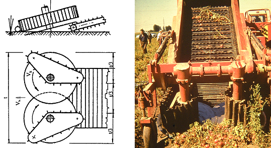
Figure 8.7 Rotating disc cutting-forwarding unit
Sieve conveyor
To remove impurities from the harvested lot sieve conveyors are used for transporting the berries inside the machine.
The slot between the sieve rods is in most cases 25mm, so the unripe, small berries as well as clods smaller than 25mm fall through the slots. According to experience, the optimal conveyor speed is 2-2.5 m/s (Figure 8.8).
After the cutting-forwarding unit, a sloped sieve conveyor is used. To prevent the plants and free berries from rolling back a reel is applied above the conveyor.
The sieve conveyors are driven and supported by cogwheels. The supporting cogwheels are often of ellipsoid shape, which vibrate the conveyor, intensifying removal.
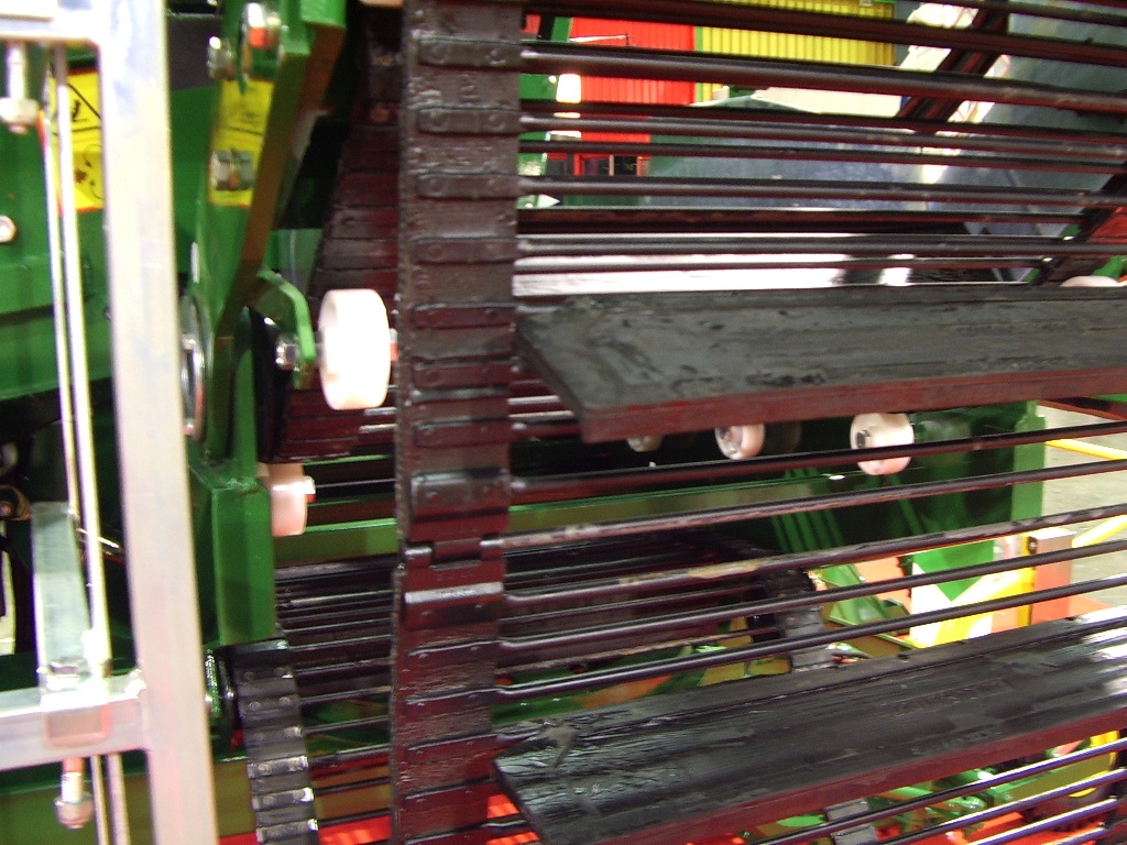
Figure 8.8 Typical sieve conveyor with rubber plates
Shaker units
They have to detach ripe berries from the plant and separate shaken berries from harvested plants.
Detaching tomato berries by shaking can be carried out in many ways. All solutions have a few common characteristics. One of them is that only the vines get into contact with the shaker unit. The whole plant is shaken through the vines giving rise to acceleration and so inertia forces in the berries. In other words, while the shaker unit accelerates the vines, the berries tend to resist the acceleration and inertia force arises between stem and berry. If the inertia force exceeds the detachment force of the berries, they will be removed.
The shaker repeats this action many times to achieve safe detaching.
The most common shaker units are the straw walker type, the longitudinal or transversal vibrating belt type and the force balanced shakers.
Straw walker type shaker
It consists of parallel laths which are fixed by bearings on two rotating crankshafts. When in use, each lath is rotating, and so do the stems sitting on them. They also transport the bushes continuously (Figure 8.9).
The inertia force which arises in the berries during shaking is composed of the centrifugal force F= m.r .ω2 and of the gravity force m.g.
The gravity force increases or decreases the inertia force depending on the position of the laths.
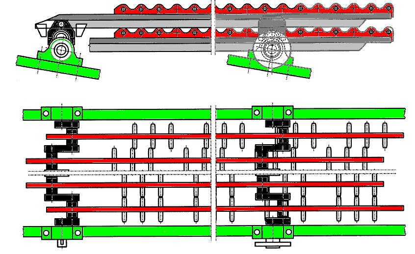
Figure8.9 Straw walker shaker beard on two rotating crankshafts
In the first case, the inertia force equals the sum of the centrifugal and gravity force. The tomato will be detached, if:
where m is the average mass of the berries
r is the eccentricity of the stage axles
F lev is the average detaching force
The crankshafts speed needed for fruit detachment is:
In case of the Hungarian made PBT type tomato harvester r = 0.05m. The average detaching force for berries in a given tomato field was Flev =5 N. In the same plantation, an average berry mass of m = 0.1kg was measured. The above data results in n = 270 1 /min, which coincides well with the recommended speed of 258 1/min.
In practice, not all berries will be detached by the first acceleration. Passing through the shaker laths, 8-12 more acceleration will affect the berries which ensure safe detachment.
Longitudinal vibrating belt shaker
These shakers have parallel belts with nails. Their motion is dual: while transporting the bushes they shake them horizontally. The detached berries fall between the belts, while the nails of the belts transport and continue to shake the plants, and finally drop them to the ground (Figure 8.10).
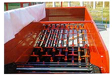
Figure 8.10 Longitudinal vibrating belt shaker
Force-balanced shaker
This shaker consists of a spokes-drum with 40-50cm long spokes and a curved grid. The drum is forced on the one hand to torsion vibration, to rotation on the other hand. The torsion vibration is due to a pair of eccentric rotating mass. The working principle of the spokes-drum is identical to that used in fruit harvesting (see Chapter 9).
The plants with the fruits get in-between the drum and the grid where the berries will be detached due to the vibration of the spokes. The removed fruits fall through the gaps of the grid. Detached plants are forwarded by the rotation of the drum and finally fall to the ground (Figure8.11).
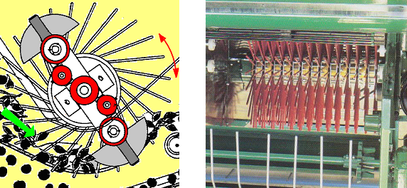
Figure 8.11 Force-balanced shaker with vibrating spokes
Cleaning unit
Clods larger than 25mm in diameter can be removed from the machines by a sloped conveyor. As the berries start to roll at a smaller slope, one can determine the optimal slope degree, at which the tomatoes start rolling back on the belt while the clods are being carried away by the conveyor.
Another method of selection is based on the difference between the specific weight of the clods and the tomatoes. Using a rotating brush cylinder, at the optimal brush strength, the clods fall through between the fibers but the tomatoes are transported away on the brush surface.
On the first tomato harvesters, a space of about 10cm was left between the first two transporting belts. Loose tomatoes and large clods fall through the space on a sorting belt. The clods were removed from the belt manually while the red berries were forwarded to the trailer. Due to this arrangement the shaker is not charged unnecessarily.
Light impurities such as leaves and parts of the vines are removed by sucking or blowling fans. In both cases, the best result can be achieved, if the mass-flow is loose (i.e. “it is flying” from one conveyor belt to another) and the airflow crosses the mass-flow perpendicularly.
Colour sorting
Colour sorting can be carried out on the harvester machine or, after harvest, in a pre-processing plant.
Nowadays, colour sorting on the machine is done by electronic colour sorters.
The working principle of those is as follows (Figure 8.11). First, the tomatoes are arranged in rows and then they pass in front of special lamps. The light reflected by the illuminated berries is processed by colour sensors and the processor of the colour sorter. Second, pneumatically driven diverters execute the decision of the built-in PC: the material will be separated in two categories: red berries and everything else (yellow or green tomatoes and clods).
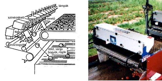
Figure 8.12 Colour sorter for removal of yellow and green tomatoes as well as clods
Construction of the tomato harvesters
According their working technology tomato harvesters can be arranged in two groups. Machines in the first one carry out the technological steps in one pass on the field, while those in the other group do less on the field, and the rest is done in a pre-processing plant. This latter procedure can be regarded as the two-stage technology.
One-pass tomato harvesters
During harvesting, when the machines work in one pass, the stems are cut under the soil surface, the bushes and berries are transported to the shaker unit, the berries are detached from the vines, and finally the leaves and other impurities are removed. The berries are sorted according to colour, and the red berries are forwarded into a transport vehicle.
The machine on Figure 22 consists of a cutter bar (1) with lifting forks above it (2), sieve conveyor ( 3), reel ( 4), forwarding conveyor belt ( 5), rotating brush clod remover (6), berry collecting conveyor ( 7), finger drum of the shaker ( 8), curved grid (9), bush transporter conveyor (10), transversal conveyor (11), fan (12), colour sorter feeding the conveyor (13), platform for the personnel sorting manually (14), colour sorter (15), long sorter conveyor (16) and discharge elevator (17).
The working principle of the machine on Figure 8.12 is as follows. The plants and the soil cut by the cutter bar get on the sieve conveyor where the soil is removed. The reel prevents the bushes from rolling back. The clods and berries on the ground fall trough a gap between the sieve conveyor and the forwarding conveyor belt onto the rotating brush where the clods fall through and the tomatoes drop on the berry collecting conveyor.
The plants travel over the gap and get between the finger drum and the curved grid of the shaker. The detached berries fall through the grid on the berry collecting conveyor, while the shaken bushes fall on the ground via the bush transporter conveyor.
A fan blows away the light impurities before the berries arrive on the colour sorter feeding conveyor. The berries passing the colour sorter get on the long sorter conveyor. Finally, through the discharge elevator, they end up in the bins of the trailer, running parallel to the harvester machine. In the colour sorter, the green and yellow tomatoes as well as the remaining clods are removed and fall on the ground. The damaged berries are removed by one or two hand sorter(s) from the long sorter conveyor.
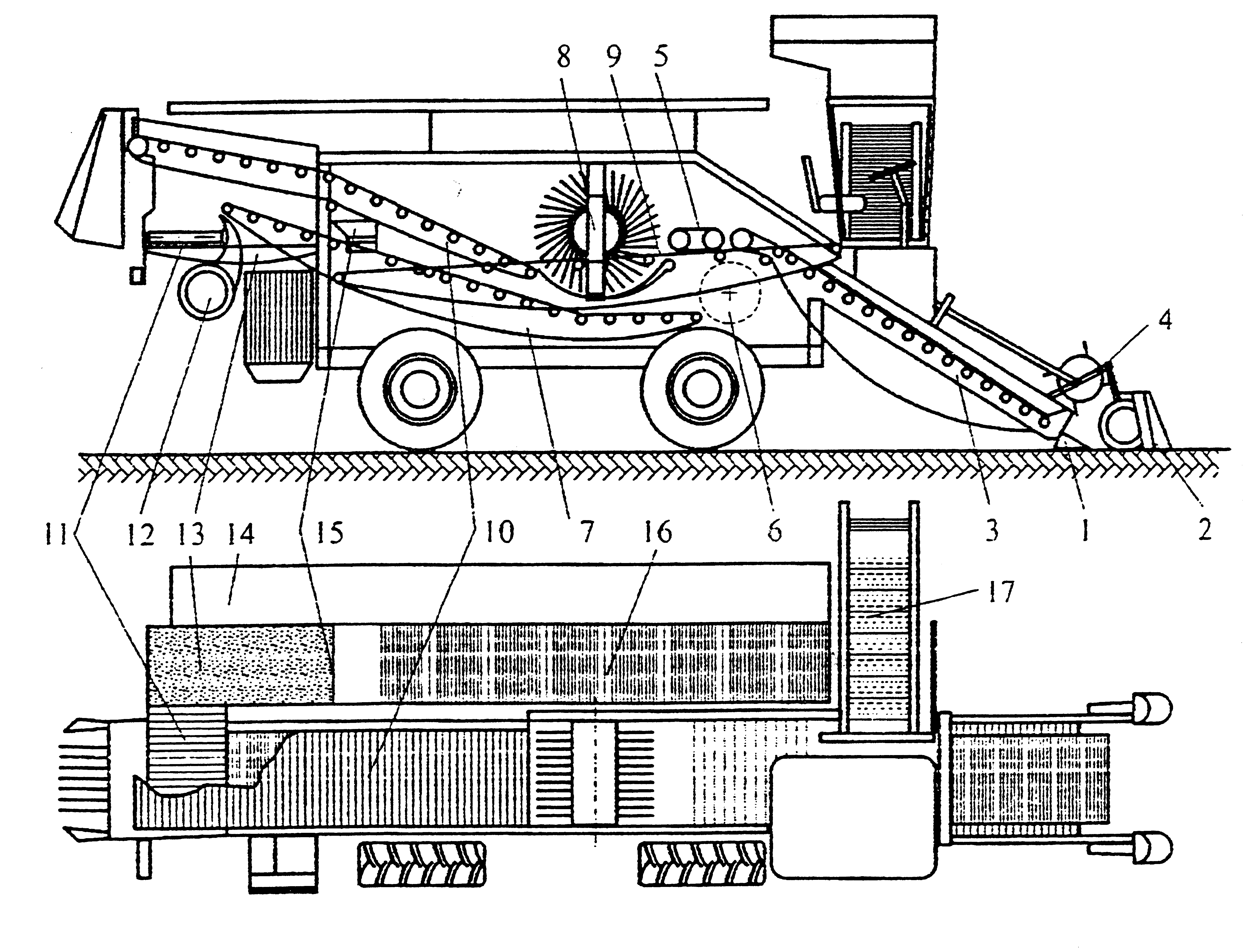
Figure 8.13 One-pass tomato combine harvester with colour sorter
1:Stem cutter, 2:lifting forks, 3: sieve conveyor, 4: reel, 5:forwarding conveyor belt ,
6: rotating brush clod remover, 7:berry collecting conveyor, 8: spoke-drum of the shaker,
9: curved grid, 10: bush transporter conveyor, 11: transversal conveyor, 12: fan, 13: colour sorter feeding conveyor, 14: platform for the hand sorters, 15:colour sorter, 16: long sorter conveyor, 17: discharge elevator
Tomato harvesting in two stages
In the first phase of the two-stage technology, a simple, tractor-towed harvester machine cuts the stems under the soil surface, picks up and transports the plants to the shaker unit, shakes off the berries from the vines, cleans, and loads the berries of different colour and also clods above a certain diameter into a special trailer (Figure 8.14).
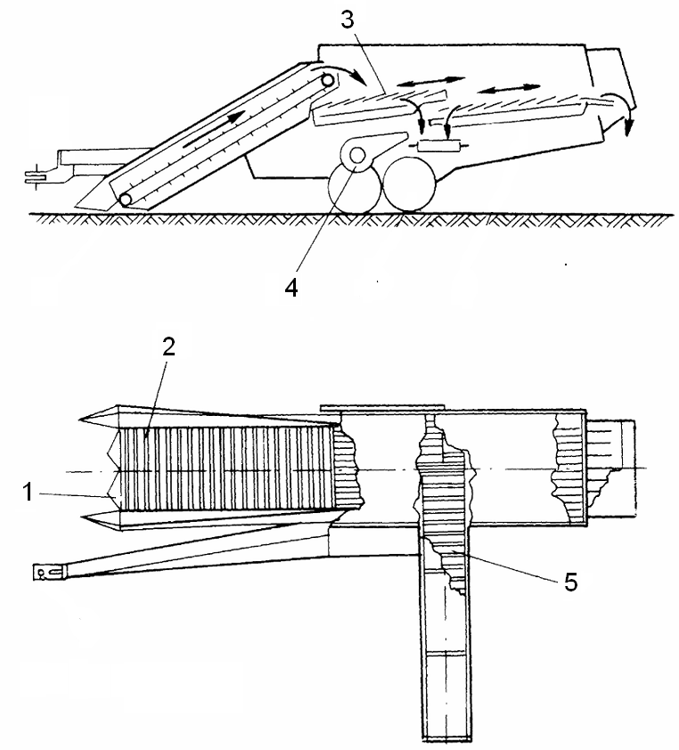
Figure 8.14 Tomato harvester machine for the two-stage harvest
1: alternating mower, 2: sieve conveyor, 3: straw walker shaker, 4: fan, 5: discharge elevator
To prevent tomatoes from being injured by clods, special, water-filled trailers are used. The water lessens the impact on the berries on the one hand, and melts and transforms the clods into mud on the other hand (Figure 8.15).
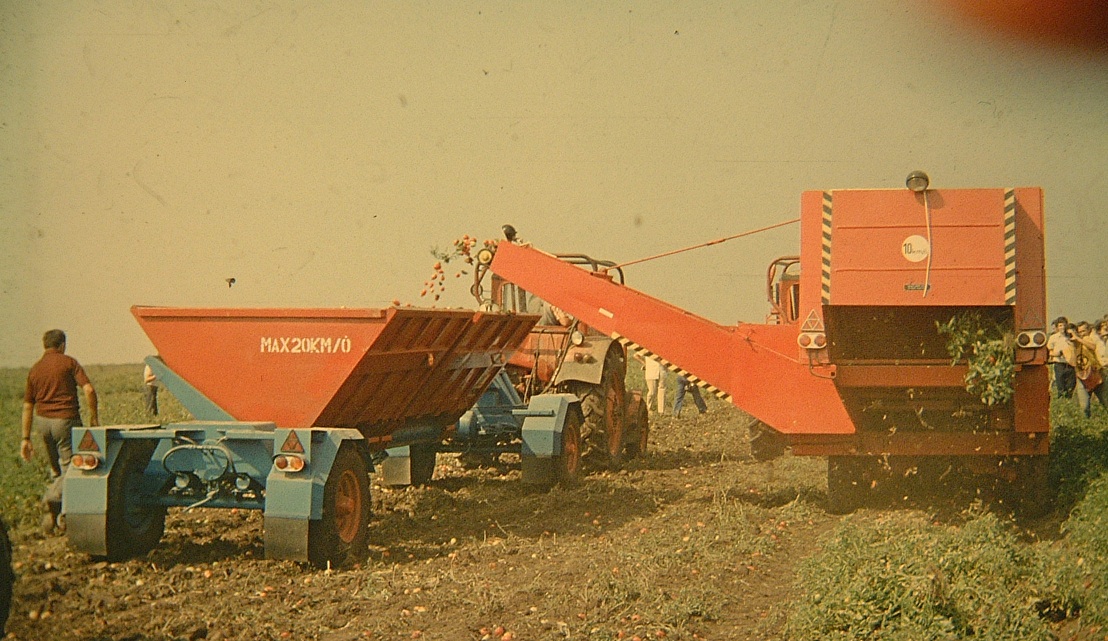
Figure. 8.15 Loading the berries into water-filled trailers
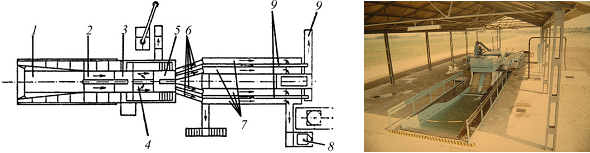
Figure. 8.16 Pre-processing plant in the two-stage tomato harvesting technology
In the second phase, in the pre-processing plant (Figure 8.16) the harvested tomatoes and mud are kipped into a pool (1) in which the water is circulated in the direction of the conveyor (2). At the bottom of the pool, high pressure air is blown into the water to help the pre-cleaning of the berries. The conveyor carries the tomatoes to the rotating-brush wet pre-cleaner (3), then impurities are removed by hand (4). After final washing by another set of water sprayers and rotating brushes (5) the berries go through distributor conveyors (6) to the selecting conveyor belts where colour sorting is carried out by hand (7). Finally, cold breaking is performed, that is peels and seeds are separated from the pulp (8). The pulp will be transported to the processing plant in tanks.
By-products such as green and yellow tomatoes, peals and seeds are used as forage.
The capacity of the pre-processing plant on Figure 8.16 is 10-15 t berries/hour.
The spitted harvesting technology, where the machines are in shelter, is more favourable for the sorting personnel than working on the platform of a harvester machine exposed to hot dust and vibrations.
Further advantage is the ability of collecting the green tomatoes and also the half-processed end product (pulp). Its disadvantage is the much higher investment cost.
Earlier, two-stage tomato harvesting was typical for Italy and Hungary. With the spread of harvester machines equipped with automatic colour sorters however it is not advantageous anymore. At present, in both countries the one-stage technology is the practice.
Detaching tomatoes with the patented Hungarian harvester machine is totally different. Only a few series of this machine have been manufactured until now (Figure 8.17).
Its main novelty is the finger drum (1). It is in frontal position and detaches the berries directly from the plants before cutting them off. The fingers are made of elastic plastic to avoid damaging the tomatoes upon contacting them. As a result of their strength however they are able to detach the berries and forward them into the machine.
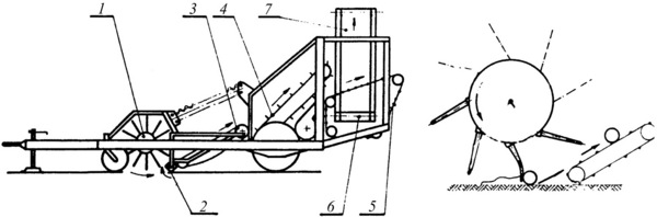
Figure 8.17 Tomato harvester detaching the fruit directly from the plant
A rotating rectangular axle (2) on the soil surface helps the tomatoes to get onto the sieve conveyors (3, 4) and pulls the plants out of the soil. The detached berries, clods and harvested plants travel on the grid conveyor to a selecting sieve conveyor (5) where the berries and plants are separated. The berries get on the discharge elevator (6, 7) while the plants fall on the ground. A fan positioned between conveyors 4 and 5, blows the light impurities away.
The work quality of the patented machine is similar to that of the earlier ones. Its mass and power demand however is much less than those of a similar machine with a shaker unit.
Comparison of harvester machines using the two types of technology is shown in Table 8.1.
Table 8.1 Technical data of harvester machines in one and two-stage harvests
|
Technology |
One step |
Two stages |
Two stages |
|
Made by: |
GARESI self-propelled |
PB-20 town |
PAS town, finger drum combing |
|
Width of harvesting: |
1.5 m |
1.6 m |
1.6 m |
|
Working speed range: |
1.1-1.8km/h |
1.8-3.6km/h |
1.8-3.6km/h |
|
Area performance: |
0.4-0.8 ha/h |
0.3-0.5 ha/h |
0.3-0.5 ha/h |
|
Mass flow: |
15-25 t/h |
10-15 t/h |
10-15 t/h |
|
Personnel: |
2-4 |
1 tractor driver |
1 tractor driver |
|
Engine power: |
88 kW |
- |
- |
|
Weight: |
8,000kg |
2,300kg |
1,350kg |
Some quality indicators of the tomato harvester machines
The main data on field tomatoes are changing from year to year and from growing area to growing area. The figures below represent extreme values experienced during several years. Consequently, the data is only for information purposes, all in yield %.
Ripe, red berries, when harvested: 60-80 %
Red, ill berries: 5 -23 %
Rotten berries: 3-13 %
Green and yellow berries: 4-6 %
Vine mass ratio in the plant: 4-12 %
In the harvested lot:
Damaged berries 0-2 %
Vine residues 0-0.3%
Soil and clods 0.5-4 %
Loss on the field: 5-28 %
8.3.2 Mechanical green pea harvesting
Fresh market green pea is still manually harvested, since no machine is available for picking the pods separately from the stems. Green pea grown for the processing industry has been mechanically harvested for decades. The harvested product is the threshed pea which loses its quality very fast.
In the 1960s and 1970s, tree different technologies were developed.
The latest machines perform those tasks in one pass, which were carried out earlier in two or three passes. Whether in one or more passes, the machines mow or comb the plants and forward them to the thresher. There the pods get open and the peas pop out as a result of the thresher’s impact and rubbing. Seeds, straw and small parts are separated from one another, and finally the seeds are collected in the hopper.
Specialities of the green pea plantation
Applying the once-over mechanical harvesting technology, the entire plantation should ripen simultaneously. Seeds are drilled in rows with equal row distance and without tractor paths. To keep harvesting loss low, a well tilled and levelled flat field is needed. Otherwise the cutter bar cannot reach the plants hidden in the trenches and the grooves.
Because the quality of the seeds deteriorates quickly, harvesting must be carefully planned. Seed quality is characterised by tenderness and is measured in Tenderometer grades. During ripening there is a 3-4 grades increase/day. After threshing, the increase is faster: 1unit/hour.
Quality deterioration can be slowed down, if the seeds are artificially cooled during the transport from the field to the processing plant.
The grower must face the dilemma of quality versus yield, because with time the quality of the product deteriorates, but the yield increases. In practice, quality has got priority, because the selling price depends on quality rather than on quantity. (If a certain number of Tenderometer grades are exceeded, the product gets worthless).
Harvest in three, two and one stages
In case of the three-stage green pea harvesting technology, the first two stages are identical to those of forage harvesting: first mowing the plants into swath, then picking up the swaths and transporting them in a pickup trailer.
In the third stage, the green pea is threshed in a threshing plant, using stable threshers. It means that the seeds and the green pea straw are collected at the spot.
The two-stage technology assumes the existence of a mobile threshing machine with an automatic levelling system enabling work on the field. In the first stage, the task is still the same, namely the green pea is mowed into swath. In the second stage, however, the mobile machine picks up and threshes the swaths. The threshed seeds are collected in the hopper of the machine and the straw falls on the ground.
The one-stage harvesting technology means using a single machine. It mows or combs off the pods, leaves and stems, then threshes the green material. The seeds are collected in the machine’s hopper and the straw falls on the ground.
Machines in the three- stage technology
Mowing the plants into swath is carried out either by special mowers (Figure 8.18) or by a special mower pickup carried by conventional combine harvesters. To avoid losses the pickup unit must follow precisely the soil surface and the fingers of the cutter bar must be equipped with vine lifters. The usual stubble–height is 4–6 cm. Figure 8.18 shows a self-propelled mower machine.
A few hours after mowing, a special trailer picks up and transports the green material to the threshing plant. Pick-up trailers used in forage harvesting can be applied in green pea harvesting as well. The mower-loader machines used earlier have lost their importance by now.
Figure 8.19 shows a pick-up trailer.
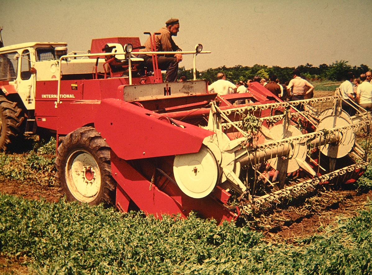
Figure 8.18 Self-propelled mower in the three-stage green pea harvesting
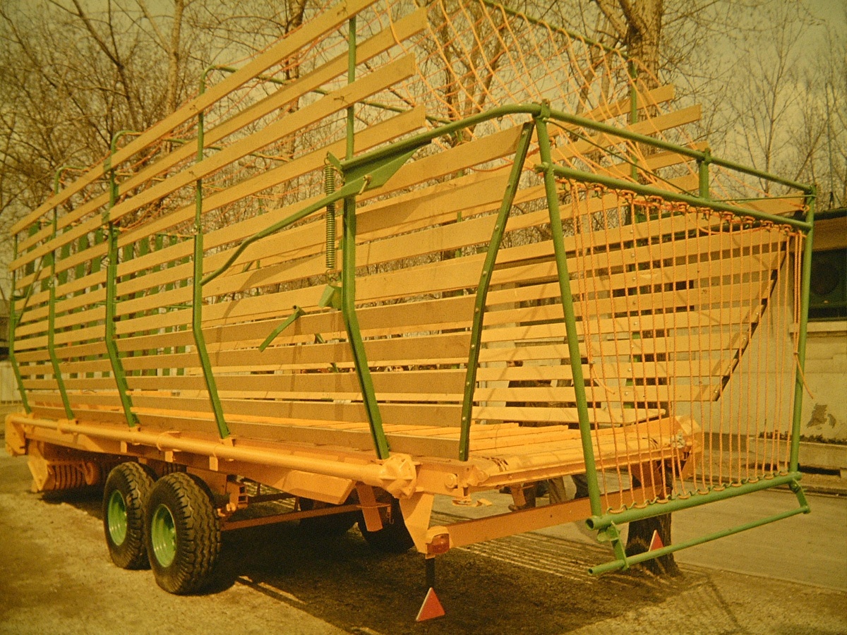
Figure 8.19 Pick-up trailer in the three-stage green pea harvesting
The harvested green pea on the trailer will be emptied into the hopper of the threshing plant which serves as a buffer storage. From there each thresher machine is supplied with un-threshed material. The input is regulated so as to maintain uniform threshing quality.
Figure 8.20 shows a stable thresher machine. A regulator can be seen on the front of the picture on the right side. Its task is to ensure the even feeding of the thresher.
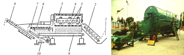
Figure 8.20 Stable green pea thresher
The working principle of the stable thresher is explained on Figure 8.20. From the hopper (1) the mowed material gets on a conveyor (2) which feeds the thresher. The thresher unit consists of an external and an internal rotating drum. The external drum (5) is a steel screen with about 1 cm2 slots. The internal drum (4) is a cylinder supplied with threshing wings (3) on its surface.
The internal and external drums turn in the same direction at different speeds. For the internal drum ni= 200 1/min, for the external n e= 25 1/min. The speed of the internal (threshing) drum and the angle of the threshing wings can be adjusted to regulate the output of the thresher. The mass flow through the thrasher is ensured by the inclined position of the drums in 3 degrees to the horizont.
Threshing happens between the two rotating drums while the input material is moving through the thresher. The wings of the thresher drum open the pods by hitting them. The speed difference between the drums causes rubbing which helps the seeds out of the pods.
Threshed seeds and smaller plant parts fall through the external drum onto the long transporting belt (9) which feeds the inclined cleaning apron (7). It forwards the non-rolling parts, but the seeds and unthreshed pods roll back onto the seed collecting conveyor (10). The straw leaving the thresher contains a few percent seed. To retrieve those seeds, the straw runs through the straw-walker (6), from where the conveyor (8) transports it on a stack.
The seed output of the Hungarian NBC machine is 1.2–2.2 t/hour.
Figure 8.21 shows a typical threshing plant arrangement. Threshers are used in groups of 2, 4 or 6. The green mass mowed on the field is moved into a puffer store (1) which supplies the threshers (2). The seeds are collected on a transversal conveyor (3) which transfers them through a sloped conveyor (4) into the cleaner (5). From the cleaner the seeds are carried on another conveyor (6) into the seed bunker (7). The straw is also collected by conveyors (8, 9, 10). Thereafter, it is chopped and collected in the straw bunker (11) or is stacked.
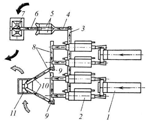
Figure 8.21 Green pea threshing plant with 4 machines
Loss resulting from threshing consists of un-threshed pods, broken seeds, and seeds remaining in the straw. Their aggregate amount is between 6-10%. If the speed of the threshing drum is increased, the result will be fewer un-threshed pods, but a higher ratio of broken seeds. The impact energy from rotation must be enough for opening the pods but not for breaking the seed.
The maximum allowed peripheral speed of the wings vper can be calculated with the following equation:
where: average energy needed to break the seeds
average mass of the seed
peripheral speed of the wing
average energy needed to open the pods
average mass of the pods
Machines in two-stage harvesting
The working principle of the stable threshing machine shows that there are two elements: the threshing drum and the tilted cleaning apron which must be kept in a stable position, otherwise threshing and cleaning will be imperfect. If the machine tilts, the straw will run through the drums too fast or too slow (or even return). Due to the tilt also the cleaning apron will not work properly. Either the seeds would be transported away with the impurities or the impurities would roll back with the seeds. This means that working with the stable thresher machine on the field would result in high losses.
In the two-stage technology the machine must be levelled. Electro-hydraulics used from the middle of the 1970s met this requirement.
The scheme of electro-hydraulic levelling is shown on Figure 8.22.
The signal for levelling is given by a pendulum of about 1m long, fixed to the frame of the machine, as shown on Figure 8.22. Its head is surrounded by four micro-switches, one in the front, one behind it, one to its left and one to its right. If the frame is in horizontal position none of the switches comes into contact with the head of the pendulum. When the machine tilts longitudinally, the pendulum’s head pushes the front or rear micro-switch. The micro-switch closes an electric circuit which opens electromagnetic valves. The valves allow the hydraulic fluid to push out or pull back the hydraulic cylinders of the wheel frames on both sides until the pendulum returns to its vertical position.
When the machine tilts in transverse direction the hydraulic fluid will be pumped from one side to another until the frame returns to the horizontal position.
Figure 8.22 The scheme of electro-hydraulic levelling
Figure 8.23 shows the levelling of a harvester machine on longitudinal and vertical slopes.
In the first stage of the two-stage technology, the plants are mowed into swaths (see earlier). In the second stage, the mobile harvester picks up and threshes the swaths in the field.
Figure 8.23 Self-propelled green pea harvesters in levelled position
Figure 8.24 shows the main parts of a towed green pea harvester machine.
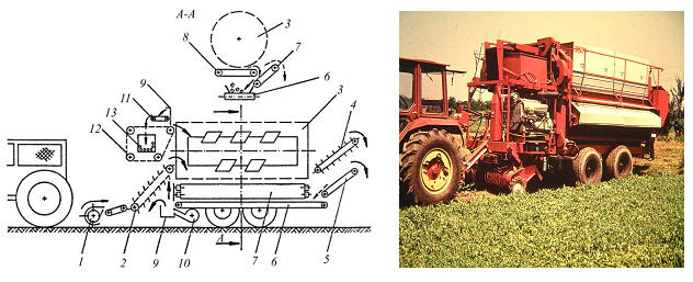
Figure 8.24 Main parts and working principle of a towed green pea harvester
Pick up unit (1), Sloping conveyor (2), External drum (3), Straw walker (4), Sloping cleaning apron (5), Seed collecting conveyor (6), Sloping cleaning apron(7), Horizontal conveyor (8),
Bucket elevator (9), Fan (10), Bunker filling conveyor (11), Pod separator (12), Seed bunker (13).
The mass flows through the harvester similarly to the stable machine. Seeds, un-threshed pods, and broken parts/impurities fallen through the screen of the external drum get on the sloping cleaning aprons (5 and 7). From there the seeds and un-threshed pods roll down onto the seed collecting conveyor (6). Seeds released from the straw in the straw-walker get also on the same conveyor. At its end, the fan (10) blows the light impurities away and the seeds and un-threshed pods fall into the bucket elevator. From the elevator the seeds are moved into the bunker by the bunker filling conveyor and pod separator. Un-threshed pods are returned to the threshing unit.
When filled, the bunker can be pushed out sideway and tilted into the transport vehicle. The main differences between this harvester and the stable machine are the bunker, the undercarriage, a separate diesel engine and the levelling system.
Machines in the one-stage harvesting technology
These machines mow green pea by a cutter bar or comb it by a picking reel, then pick up, thresh, and clean the green mass in the same machine. As harvesting and threshing are carried out by the same machine, we may call it a combine harvester.
When using a picking reel, the picking fingers detach, in addition to the pods, most of the leaves but the stems remain on the ground. Because less green mass is picked up, the thresher’s capacity is higher than when harvesting is performed by mowing.
A green pea combine harvester with a picking reel is shown on Figure 8.25. The harvester works similarly to the machine used in the two-stage technology: the picking unit consists of the picking reel (1) and the levelling roller (2). The combed material gets onto the first sloping elevator (3), then on the thwart conveyors (4). Two more conveyors (5, 6) forward it between the external and internal drums (7, 8, 9). The screen drum is cleaned by a cylindrical brush from the outside (10). The seeds are moved into the tank (17) through the sloping cleaning apron (11), the seed collecting conveyor(12), via the bucket elevator (13), the bunker filling conveyor (14) and the pod separator (16).The light impurities are removed by the fan (15).
The machine is driven by its front wheels and steered by the smaller, rear wheels. The engine is placed behind the driver’s cabin.
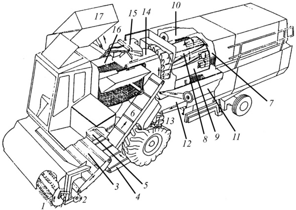
Figure 8.25 Main parts of a self-propelled green pea harvester
The latest harvesters are equipped with more than one threshing drums to increase the capacity of the thresher. Using more threshing drums forces the green material to go a longer distance in the screen drum, thus, it is exposed to more impacts and the rubbing surface increases which results in more intensive threshing.
Some data of two machines in the one-stage technology are shown in Table 8.2.
Table 8.2Comparison of one-stage green pea harvesters
|
Made: |
VNBC-F (towed) |
BK-3F (self propelled) |
|
Working width: |
1 path |
3 m |
|
Speed limit: |
1.1-1.8 km/h |
1.2-1.9 km/h |
|
Area performance: |
0.3-0.5 ha/h |
0.4-0.8 ha/h |
|
Mass flow (threshed peas): |
0.8-2.5 t/h |
2-3 t/h |
|
Tank size |
0.8 m |
1 m |
|
Engine power: |
75 kW |
120 kW |
|
Weight: |
9.6 t |
13.5 t |
8.3.3 Green bean harvesters
Although the quality of mechanically harvested green bean meets the requirements of fresh market product, most of it is canned or deep-frozen.
Picking fingers detach the pods from the vines. The elastic fingers made of spring steel are fixed to the picking reel. When the machine moves forward the elastic fingers of the rotating picking reel extend into the bean bushes and pick off the pods by their pedicle (see Figure 8.26). Together with the pods, leaves and broken vines are also detached.
The fingers with a high peripheral speed (4–5.5 m/s) forward the detached material onto a belt conveyor. The cover above the reel helps forwarding. The machine’s powerful suction and blowling fans remove leaves and other field debris. Mechanical sorters help to separate the detached pods from other plant parts. Beans are collected in tanks or on a trailer.
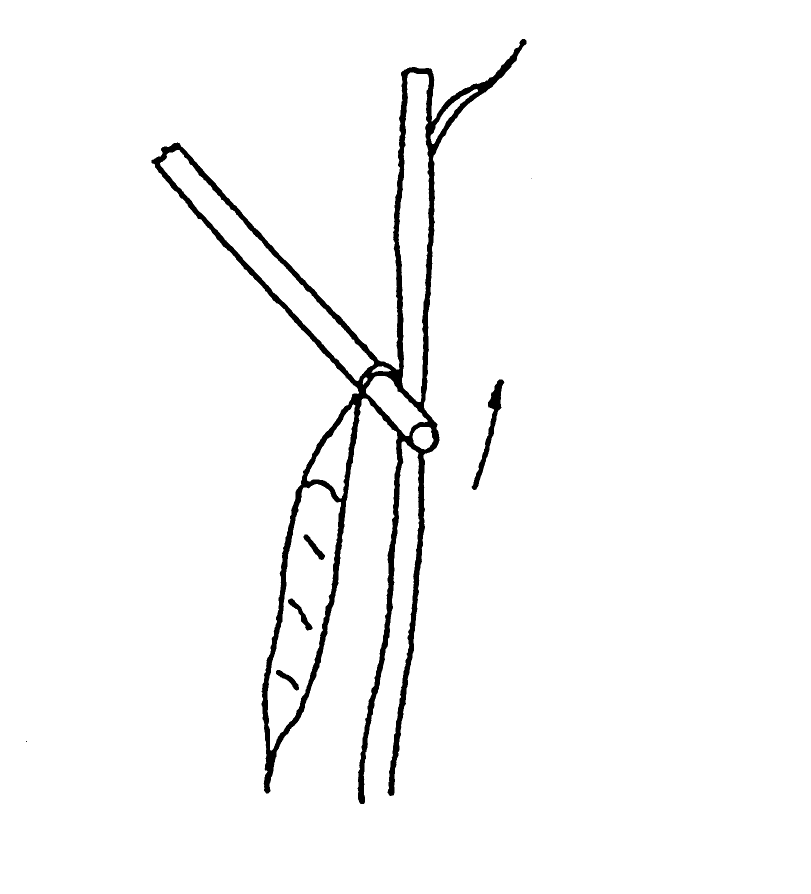
Figure 8.26 Interaction between the steel finger and the green bean pod
Specialities of the vegetation in mechanical harvesting
Even bush height and hanging type pods are preconditions to effective combing. The appropriate varieties have straight, cylindrical pods. Dense population is needed to hold up the bushes during pod detachment and to catch the pods flying out from beneath the picking reel cover. The minimum row distance is limited by the type of harvester machine (see later). The plant must be firmly attached to the soil, the pods have to be different in size and shape from the leaves and stems, and they must have a curved pedicle. Soil surface must be even to prevent the fingers from touching it.
Main parts of the green bean harvesters
All machines consist of a picking reel, with cover above it, of cleaning system, and of forwarding and collecting units.
Picking reel
It consists of a cylinder with picking fingers fixed to the surface of the reel. (Figure 8.27). The distance between the fingers is generally 5–6cm, the length of the them is 21-5cm, the diameter at the tip of the fingers is between 50-70cm.
The maximum peripherical speed of the combing fingers should be around 4 -5.5m/s for a forward speed of approximately 0.5 m/s.
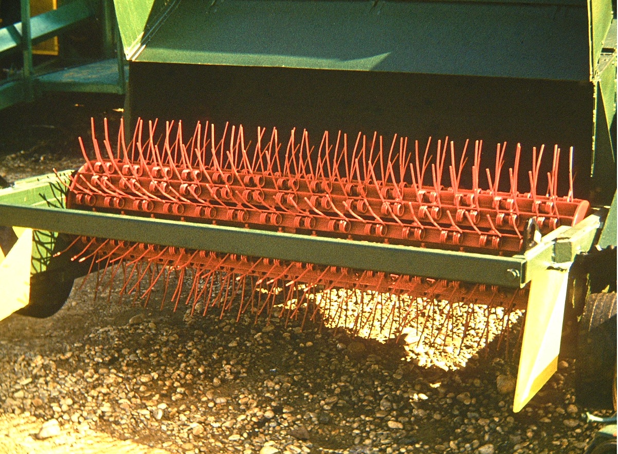
Figure 8.27 Picking reel with picking fingers. The cover is in open
Depending on the picking reel’s relative position to the direction of the rows, we may distinguish between longitudinal and transversal picking units (Figure 8.28).
The longitudinal reel runs parallel to the plant row; it picks one row at a time. It is set in a tilted position with its front higher than its back (Figure 8.29). Accordingly, the combing of the plants starts from the top resulting in fewer bunches and broken pods. This means higher product quality. The disadvantages of this arrangement are that productivity is lower and the investment costs are relatively high.
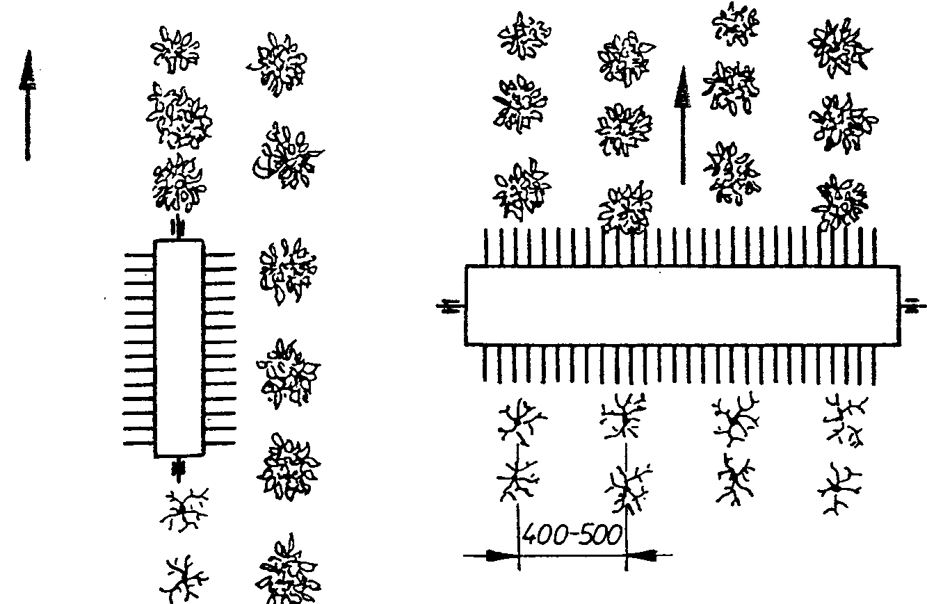
Figure 8.28 Longitudinal and transversal picking units
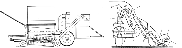
Figure 8.29 Side and front view of a green bean harvester with longitudinal picking unit
Depending on the length of the reel, harvesters with transversal frontal picking reel can comb many rows at the same time. This leads to higher productivity and reduced costs.
In this case, however, the fingers comb the plants from the bottom to the top. The fingers must pass through the whole plant. As a result, many bunches will be detached. Sometimes even whole plants are pulled out. Because the pods at the bottom must get through the whole plant before being forwarded onto the conveyor belt, they often contact the fingers. That is the reason for the many broken pods when using this harvesting technology (Figure 8.30).
Figure 8.30 Self-propelled green bean harvester with a transversal picking unit, supplied with a sloping belt
The cover of the picking reel
The task of the cover in front of and above the picking reel is to guide the detached pods into the machine. Figures 8.29 and 8.30 show their position on the machines with longitudinal and transversal reels.
The front edge of the cover on the machines with a transversal reel largely influences the extent of loss. If the edge is positioned too deeply, although the loss decreases, the plant is pushed forward creating an unfavourable position for combing.
If the edge is lifted too high, many pods will be released below it.
To improve the work quality of the machines with a transversal reel, either air blow, or a sloping belt, or a rotating brush is placed in front of the cover. These elements turn the top of the plants in front of the combing reel with a speed higher than the travel speed. Now, the combing starts from the top and results in fewer broken pods (see Figure 8.30).
Cleaning system
The task of the cleaning system is to separate all detached plant parts from the single pods, including bunches.
Bunches are those detached parts of the plant which consist of at least one pod and other plant parts (stalk and/or leaves).
The cleaning units in the machine can be sieve conveyors, bunch remover aprons, in some cases, bunch cutters, and suking and blowing fans.
The slot between the elements of the sieve conveyors is no more than 5mm. It has to eliminate eventual small soil and plant parts. The suking and blowing fans remove all the detached plant parts, except for the pods and bunches. In each case, it is possible to control the air speed. It must be carefully set to avoid the removal of the pods.
The bunch remover has to separate bunches from the individual pods. Bunches must be removed because they would cause difficulties in the processing technology.
A bunch remover consists of tilted aprons with steel nails on the surface. The length of the nails is 10-12cm and the distance between them is about 15cm.
Figure 8.29 illustrates their working principle. The whole combed mass is moved onto the bunch remover (4) which transports it upwards. The individual pods fall between the nails onto the pod collecting conveyor (7), while the bunches are forwarded upwards. If there is another bunch remover, it receives all bunches from the first unit and separates them again from the individual pods. Finally, all bunches left on the second unit fall on the ground.
Some earlier machines were equipped with bunch cutters. A bunch cutter consists of a sieve conveyor with large, 10cm wide gaps and a cutter bar underneath (Figure 8.29, 5). The bunches fall on the sieve conveyor from the last bunch remover. Those which “sit“ on the rods of the conveyor are transported to the cutter bar which cuts off the pods. Other bunches fall simply through the gaps to the ground.
Collecting the harvested product
In most cases, the individual bean pods going through the cleaning system are collected in the hopper of the harvester machine. Typical capacity is 2-4 t. After being filled, they can be tilted and emptied into a transport vehicle.
Because of its high prize the self-propelled bean combine harvester on Figure 8.30 is economical if used on plantations above 300 ha. In most cases, the processing industry or partnerships own these machines.
Table 8.3 includes the main characteristics of a bean plantation before harvesting as well as the quality parameters of the harvested lot.
Table 8.3 Main characteristics of a bean plantation before harvesting
|
Measured value |
|
|
Total green mass |
30-38 t/ha |
|
Yield |
14-21 t/ha |
|
Harvested mass |
10-14 t/ha |
|
Harvested unhurt pods |
65-80 % |
|
Pods with minimal damage |
10-24 % |
|
Impurities |
1-4 % |
|
Soil residues |
0-0.4 % |
Table 8.4 compares two green bean harvesters with transversal picking reels.
Table 8.4 Main technical data of two green bean harvesters
|
Make: |
Pixall |
Ploeger |
|
Type: |
Beanstalker |
BP-700 |
|
Harvested width |
3.05 m |
3.1 m |
|
Speed range: |
0.....35 km/h |
0.....24 km/h |
|
Mass flow: |
6.....7 t/h |
6....7 t/h |
|
Tank capacity: |
3.6 t |
2.3 t |
|
Engine power: |
106 kW |
157 kW |
|
Weight: |
10.3 t |
10.5 t |
8.3.4 Mechanical harvesting of onions
The basis for the development of the first onion harvester was the potato harvester machine. The task is similar: the vegetable must be picked up from the soil, then it must be sieved, weeds and haulm must be removed, and finally it must be poured into the bunker-hopper.
In some cases, before harvesting the vegetation must be topped.
Some harvesters are able to pick up onions grown in one and two years (one-year technology: from early seeding to harvesting everything is carried out in the same year. Two-year technology: seeding and harvesting seed onion in the first year, harvesting whole size onions in the second year).
Harvesting can be carried out in one or two stages. Harvesting in one stage means digging, pre-cleaning, and forwarding the onions into the bunker-hopper or on the transport vehicle.
Harvesting in two stages means digging, pre-cleaning and windrowing in the first stage, sieving, weed and haulm removing, and forwarding in the bunker-hopper or on the transport vehicle in the second stage. Between the two stages the onions dries on the fied to enable their long term storage.
Specialities of the vegetation for mechanical harvesting
Onion is grown on flat arable land or on ridges (in Hungary 1.6 m wide).The usual distance between plant rows is 25–30 cm, between the plants 8–12 cm. Soil surface should be flat, without clods and weed. Harvesting should possibly start when the stems are already dry (in this case topping is not needed).
Main parts of the onion harvesters
Some of the many harvester types are suitable for working only in the one or only the two- stage technology. Others are able to work in both technologies.
However the main parts of all onion harvesters are similar and are applied on all machines.
Cutting-forwarding unit
In both technologies the first step is to dig out the onion from the soil. To avoid damage, a certain amount of soil is dug up as well. That is the reason for using a cutting-forwarding tool which can cut below the roots of the plants. Rotating flat discs, spherical discs and rotating square axles are used for this task.
Spherical discs are used in the two-stage harvester shown on Figure 8.31. For each plant row a spherical disc (1) is fixed separately on the V shape frame (2), which enables the following of the soil surface individually. The spherical discs turn out the onions from the soil and windrow them.
Figure 8.31 Spherical discs as cutting-forwarding units
Rotating square axles are also able to lift the onions out of the soil (Figure 8.32). Their main parameters are the edge size of 35-40mm, and the peripheral speed of 70–75 m/s. The unit shown on Figure 8.32 with the indicated direction of turning digs the onions continuously out of the soil. Because of its high towing resistance they are used mainly in ridges.
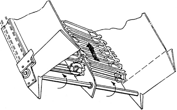
Figure 8.32 Rotating square axle as cutting-forwarding unit
Sieve conveyors
In both harvesting technologies the picked up soil must be separated form the harvested lot. For this purpose sieve conveyors are used with 25 mm gaps.
Swath laying tools
In case of the two-stage harvesting technology, in the first stage the onions are laid in swath. Before laying the onions on the ground, the soil surface is levelled with a leveller plate. This makes work easier in the second stage when onions are picked up. (Figures 8.31, 4 and 5).
Pick up unit
In case of dry, hot weather in the two-stage harvest onions are picked up off the soil only after a few days. During this time the leaves of the onions dry out so the product is protected from external contamination. The machine parts used for picking up onions from swath are basically the same as used for digging (Figure 8.33).
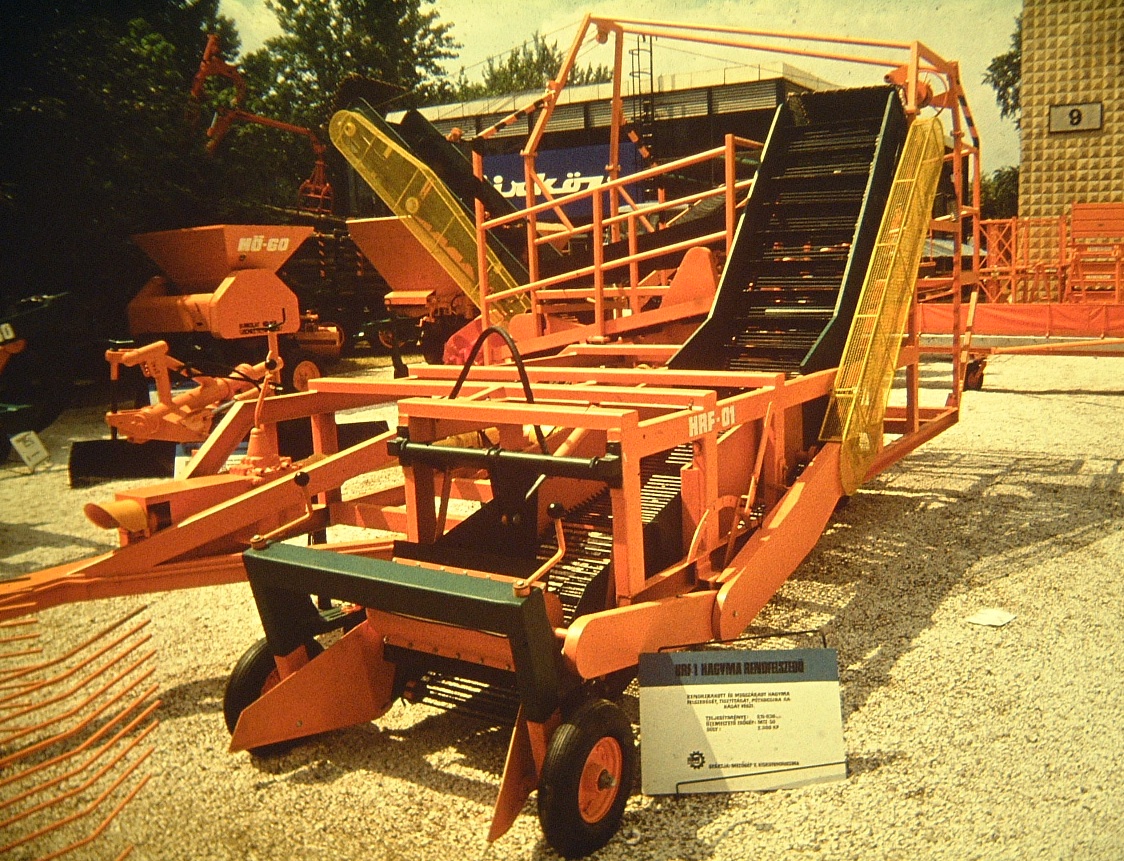
Figure 8.33 Machine used for picking up the onions from the swath
Cleaning tools
The onions picked up travel again on the sieve conveyor, then air cleaning and, if necessary, the manual removal of damaged and ill product follows.
In addition to the already mentioned sieve or bar-chain conveyor which removes the soil, a fan with blowing air flow and counter-rotating rollers which strip the dry stems and also the weeds off the onions, are the most commonly used cleaning units of the harvesters.
The fan is placed underneath of the upper end of the sieve conveyor so the air flow crosses the harvested onion mass-flow in the air before arriving on the discharge elevator.
The counter-rotating rubber rollers are placed so as to trap the flying long and thin plant parts, like weeds. The rollers sever these parts from the rest of harvested mass by pulling them. They also catch the onion stems, and - based on the different diameters of the stem and the onion - they strip off only the stems.
De-stemming of onions can be carried out by an inclined surface made up of rubber rollers or helix-shaped structures attached to the rollers. Here also the rollers trap the long and thin leaves of the onions, and sever them from the onion by pulling.
The manual removal of damaged and ill product is done while the onions are transported by an oscillating sieve.
As a result of these cleaning steps the onion is ready for long term storage under controlled air conditions.
The machines on Figures 8.31 and 8.33 show examples of the elements in the two-stage technology. In the first stage the spherical discs connected to a frame in front of the tractor dig out the onions. Behind the tractor a sieve conveyor (3) lifts the onions, sieves the soil, and levels the ground (5), then lays the onions back on the ground (4) in swath.
The machine in the second stage of the two-stage harvesting technology performs the following steps:
It lifts, sieves, cleans and, discharges the onions. The workers standing at the oscillating sieve are separating clods and damaged/ill onions.
The discharge elevator forwards the onions to a trailer towed by a tractor moving beside the machine.
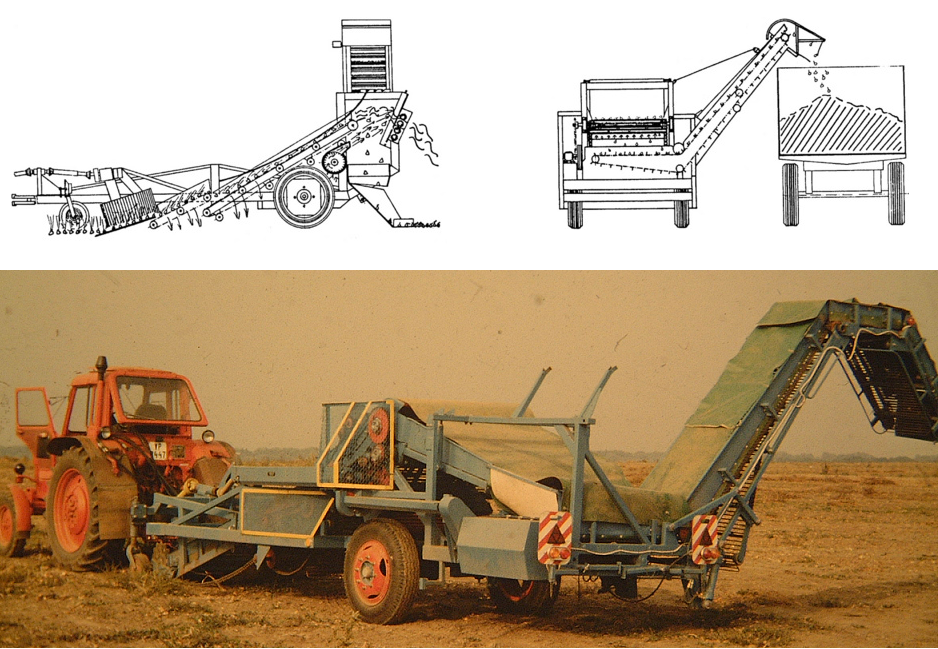
Figure 8.34 Onion harvesting machine for one and two stages
Machines used in the one-stage technology are generally able to harvest also in two stages. However if the machines suitable for the one–stage technology are to be used in the two-stage technology, some modification must to be made. If the cutting-forwarding unit is a pair of flat discs and is to work in the one-stage technology, it must run deeper in the soil. After sieving and cleaning the onions it discharges them on a trailer.
In case of the two-stage technology, in the first stage the rotating flat discs run less deep and a chute replaces the discharge elevator so after levelling the soil surface the onions are laid down on the ground in swath.
In the second stage the discs are running less deep and a discharge elevator fills the trailer.
To change from the one-stage technology to the two-stage technology, the discharging conveyor is turned 900 along a vertical axle. Figure 8.34 shows an onion harvester in both, one- and two-stage harvesting position.
Table 8.5 contains the main parameters of a harvester machines line for two-stage technology.
Table 8.5 Technical data of an onion harvester in two stages
|
Made: |
TRIO-I (1. pass) |
TRIO-II (1. pass) |
TRIO-III (2. pass) |
|
Width of harvest: |
1.8 m |
- |
1.3 m |
|
Mass flow: |
14-20 t/h |
14-20 t/h |
20-24 t/h |
|
Tractor power: |
57 kW |
57 kW |
57 kW |
|
Weight: |
570 kg |
540 kg |
3100 kg |
8.3.5 Mechanical harvest of cucumber
The problem of mechanical harvesting of cucumbers destined for both fresh produce markets and processing was technically solved decades ago. It is not the technical imperfection of the machines which lead to the fact that mechanical cucumber harvesting is used less and less. The main problem is the uneven ripening of the cucumbers. Due to the once-over technology significant yield might be lost, including the most valuable smallest cucumbers, the picklings.
All once-over cucumber harvesters work according to the following method:
-
lifting the plants lying on the ground,
-
cutting the roots below the ground surface,
-
picking up the plants and transporting them to the stripping rollers,
-
impurities will be blown away by air flow, and
-
cucumbers are collected on a trailer or in containers
Specialities of the vegetation in mechanical harvesting
As the plants are lying on the ground the soil surface should be flat and without clods. Genotypes with high yield should be selected. A twin row distance of 20–30cm and 90 cm, a plant-to-plant distance of 10 cm in the row is recommended. This results in a plant number of about 200,000 per hectare.
Weeds with woody stems can cause trouble both for the cutting and stripping elements of the machine. Losses due to the once-over harvesting can be compensated for by second and third seedings.
Main parts of the cucumber harvesters
Plant lifting unit
Cucumber vines lying on the ground can be easily lifted. For this purpose a steel-finger pick up roller (Figure 8.35) and a pair of corrugated rubber belt pick up conveyors (Figure 8.36) are used. Whichever is used, the most important criteria is to move the plants without damaging the cucumbers.
Stem cutting unit
It cuts the lifted vines under the soil surface. Passive blades, cutter bars or swinging blades are used for this purpose. Passive blades can be used effectively only in flat soil without weeds. If the blades meet the woody weeds above the ground, they may pile up in front of tham blocking the further work.
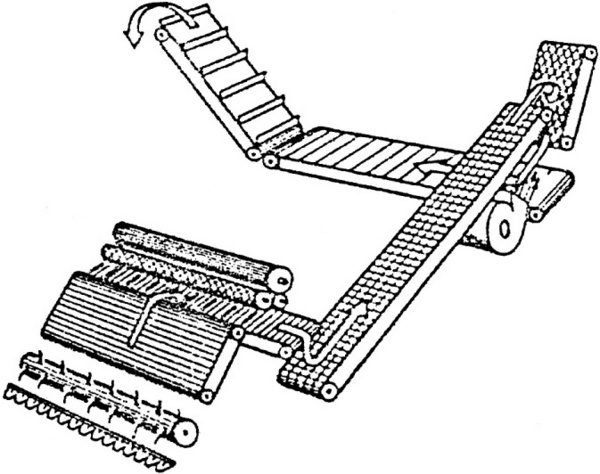
Figure 8.35 Cucumber harvester with cutter bar and steel finger pick up roller
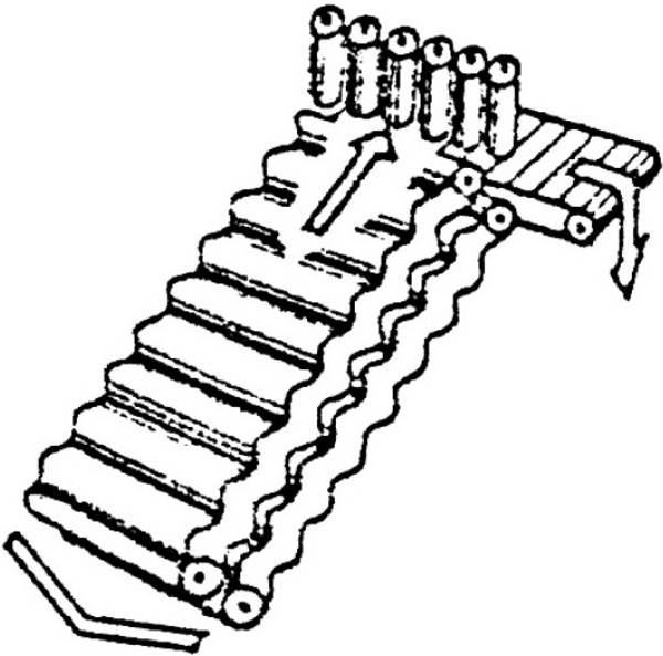
Figure 8.36 Cucumber harvester with passive blades and corrugated rubber belt pick up
Plant forwarding unit
Any conveyor belt which handles the cucumbers gently is appropriate for forwarding the plants from the lifting unit to the stripper. In the machine VU the plants are transported between the two soft corrugated conveyor belts.
Stripping unit
Cucumbers are detached from the vines by pairs of high-speed rubber stripping rollers. The rollers in each pair turn opposite to each other. They catch the vines or leaves and pull them in. As the cucumbers are much thicker than the vines, they split off the vines. The vines and the leaves exit the machine after passing through the rollers. Stripping rollers can be arranged both horizontally and vertically. The main parameters of the rollers on the harvester VU are the following: diameter: 80mm, peripheral speed: 4.5 m/s. If long stem weeds wind around the rollers, they will be stuck there. This breaks down the roller unit. By duplicating the rollers this problem can be avoided.
Cleaning of the harvested lot
Due to the pick-up technology no soil or clod fraction is to be expected. Fans blow and suck away light impurities. The fan underneath the stripping unit also helps to the plants and the rollers to meet.
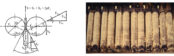
Figure 8.37 Forces acting on the stem of the cucumber and the stripping rollers.
Collecting the harvested cucumbers
In the machine the detached cucumbers fall on the discharge elevator and from there either in the machine’s hopper or into a towed trailer.
Figure 8.38 shows the Hungarian made VU cucumber harvester in work. The harvested product is forwarded into a trailer running parallel to the harvester.
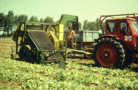
Figure 8.38 Cucumber harvester with passive blades and corrugated rubber belt pick up
Table 8.6 shows the Hungarian cucumber size standard.
The main technical date of two cucumber harvesters is shown in Table 8.7.
Table 8.6 Size standards in Hungary
|
Size |
Length (cm) |
Thickness (cm) |
|
A |
3–6 |
Till 2 |
|
B |
6–9 |
Till 3 |
|
C |
9–12 |
Till 4 |
|
D |
12–14 |
Till 5 |
|
E |
above 14 |
Till 7 |
8.7 Main technical data of two cucumber harvesters
|
Made |
VU |
Porter-Way |
|
Stem cutting unit |
passive blades |
cutter bar |
|
Vine lifting unit |
corrugated pick up conveyors |
steel finger pickup |
|
Stripping unit |
vertical rollers |
horizontal rollers |
|
Working width (m) |
1.1 |
2.0 |
|
Area flow (ha/h) |
0.2 |
0.3–0.5 |
|
Working speed (km/h) |
1.5–3.0 |
1.5–3.5 |
|
Mass (kg) |
2,300 |
2,400 |
|
Tractor power demand (kW) |
37 |
37 |
|
Main power demand |
1 tractor driver |
1 tractor driver + 1 operator |
8.3.6 Mechanical harvesting of root vegetables
The technologies described below are for harvesting carrot, parsley, parsnip, radish, and root celery.
Two basic methods are applied:
-
Digging and elevating
-
Pulling by the leaves
In both cases the following actions are needed: getting the plant out of the soil, removing its leaves, clearing the roots from the soil, collecting the roots in a trailer.
Specialities of the plantation in mechanical harvesting
For both methods an even surface is needed where the soil is loose and without stones. In most cases root vegetables are grown in ridges, the preparation of which needs special tools. Seeding must be carried out in uniform depth to achieve uniform growth. For the pulling type harvesting the plantation should be free of weeds, the plant rows must be straight, and a row distance of at least 30cm is necessary. For those root vegetables which are harvested by the pulling method, the aerial portion must be healthy and strong enough.
The harvesting technologies
Digging a nd elevation harvesting
The method comes from the potato harvesting technology. In the first stage, leaves are stripped and cut, using a mobile chopper, a flail wheel or saw discs (Figures 8.39 and 8.40). The chopped material is forwarded to an auger. The auger transports the leaves to the side of the machine.
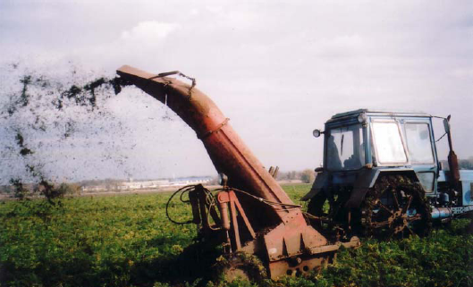
Figure 8.39 Mobile chopper in leaf stripping
8.40 video Leaf stripping with flail wheel and saw discs
In the second stage the digger spades or the discs of the harvester machine lift the roots together with a certain amount of soil and forward them to the sieve conveyor (Figure 8.41). For breaking the clods a pair of air-blown rubber rollers can be used. The clods and roots travel through the gap between the rollers. The roots get through undamaged, while most of the clods break during passage. Afterwards, the remaining soil falls on the ground through a second sieve conveyor. The process continues with work by an inclined cleaning apron with small rubber teeth on its surface. Impurities such as weeds and leave residues get stuck in the teeth, while the roots roll back on the discharge elevator. Finally they are collected in a tractor-towed trailer.
One of the advantages of this harvesting technology is that a normal potato harvester can be applied. Another benefit is the ability to harvest at least two rows at the same time. Also, harvesting is less weather-dependant.
Its disadvantage is that the headed and partly broken root vegetables are not suitable for storage, but they have to be processed iImmediately. A potato harvester used in carrot harvesting is shown on Figure 8.42.
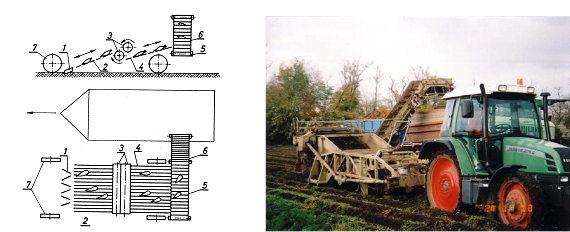
Figure 8.42 Potato harvester in carrot harvesting
1. steel plates in V arrangement to dig out the roots, 2. vibrating grill to clean and transport the roots, 3. rubber rollers breaking clods, 4. vibrating grill to clean and transport the roots, 5. and 6. carriage filling belt
Pulling harvesting
Harvesting according to the pulling principle is a one-stage technology (Figure 8.34). The machine can be towed or self propelled. The main parts of the harvester are: the pulling belts (2) which catch the leaves and lift the plants; the guiding cones (3), which guide the leaves in-between the belts; underneath the belts a subsurface coulter (1) loosens the soil in the lane of the roots. The coulter has an inclined and deep enough position so as not to damage the roots.
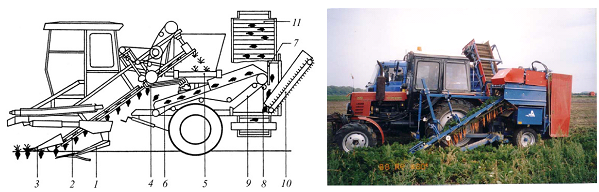
Figure 8.43 Main parts of a pulling type harvester
-
subsurface coulter loosens the earth in the plant row
-
two parallel belts pull out the plants
-
guiding cones on both side of the row to lift the leaves of plants
-
stem removal unit
-
belt to transport the removed stems to the side
-
belt to transport the carrots to the rubber tees belt (10)
-
rubber plate to direct the mass flow of roots
-
stem selector rubber roller
-
slide for the stems
-
rubber tees belt
In order to being able to pull the roots in a vertical direction, the speed of the pulling belts and the ground speed of the harvester must be coordinated. The appropriate relation between the two speeds is achieved when the horizontal speed component of the pulling belt is equal to the ground speed in the opposite direction.
At the upper end of the belts, a pair of topping implements (counter-rotating bars or rotating disks) is placed to remove the tops (4). The counter-rotating bars pull in and break the leaves, leaving them 1.5–2 cm behind. This residue protects the roots from desiccation and infections during long term storage (Figure 8.44).
The leaves fall then on a transversal conveyor (5), the roots travel on a sieve conveyor (6) to a rubber finger belt (10). This latter belt has to remove small impurities and to clean the surface of the roots. Weeds get between a fork (7) and a rubber roller (8) forwarding the weeds on the plate (9) which moves them to the ground. Roots rolling back from the belt (10) get on the discharge elevator (11).
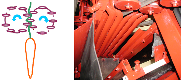
Figure 8.44 Counter-rotating topping implements
The harvesters available on the market are made for harvesting one, two or thee plant rows simultaneously. Harvesters harvesting two or three rows are equipped with two or three pulling and topping implements. Table 23 contains the main technical data of some pulling type root vegetable harvesters.
Table 8.8 Main data of two pulling type root vegetable harvesters
|
Made |
E–825 |
ASA-LIFT |
|
Rows harvested |
2 |
3 |
|
Distance of rows (mm) |
350–500 |
450–500 |
|
Forward speed (km/h) |
3.6–6 |
2.7–4 |
|
Area capacity (ha/h) |
0.15–0.2 |
0.4–0.5 |
|
Mass (kg) |
4,200 |
5,800 |
|
Power demand (kW) |
59 (tractor) |
70 (self propelled) |
|
Manpower demand |
1 tractor driver + 1 operator |
1 driver + 1 operator |
8.3.7 Mechanical harvest of leaf vegetables
Leaf vegetables, like cabbage, lettuce, Brussels sprouts, celery, broccoli, cauliflower, and artichokes can be harvested by cutting or by pulling the stalk off. Both are once-over technologies.
In case of cabbages and lettuces attempts were made also for performing selective harvesting according to the size or hardness of the plant head. These will be discussed in the subsection on the mechanical harvesting of lettuces. In careful agro-technology, the plants grow uniformly, and both harvesting technologies mentioned above can be economical and of good working quality.
Specialities of the plantation in mechanical harvesting
In harvesting leaf vegetables with the pulling method straight plant lines and a flat soil surface ares needed. Because of the once-over harvesting the plants should be the same size. The distance between the rows (450–550 mm) is determined also by the size of pick up unit.
The two harvesting technologies
Harvesting by cutting the stems
This technology starts with guiding the leaves between the driving belts. These hold the plants during the time the stems are cut. All the stems are cut at the same height above ground. Different separating devices may follow, like the separating roller sorting according to size. Thereafter, the plants get on the discharge elevator.
In case of cabbages the mechanically harvested plant can be fresh marketed, processed or stored. If harvesting is done by cutting the stems above the ground at the same height stalks with different lengths will remain on the heads. This produce is not appropriate directly for the fresh market.
Harvesting by pulling the plants off the soil
This technology is applied mainly in cabbage harvesting. The reason for pulling the heads off before cutting is to achieve uniform stalk lengths remaining on the cabbages. Here the heads are pulled off the soil by two inclined belts and guiding edges or helix-shaped cylinders. As the coulter bar is in a stable position relative to the pulling elements, all cabbages will be un-stalked uniformly.
Main parts of the harvester
The machines collect the cabbages in a bunker or discharge them in a trailer.
One or two-row harvesters are on the market. Special parts of the machines are the
-
pulling and cutting,
-
cleaning, and
-
discharging units.
Pulling and cutting unit
Vertical pulling of the plants can be achieved by a pair of inclined belts or by two counter-rotating helix-shaped cylinders. In case of cylinders the cabbages are transported on the surface of the helixes. Similarly to the pulling type carrot harvesters, the horizontal transporting speed of the belts or cylinders must be the same as the ground speed, but in the opposite direction. As the vertical speed components compensate each other, the remaining vertical speed component of the transporting element pulls the plant off (Figure8.45).
The transporting speed of the helix-shaped cylinders is the product of the speed and the pitch of the helix.
Above the pulling elements a rubber-grid conveyor runs with the same transporting speed as that of the pulling elements. Its task is to hold the cabbage heads during cutting and transport them to the cleaning unit.
The stalks are cut by a rotating or alternating knife which is placed underneath the guiding edges of the belts or between the helixes.
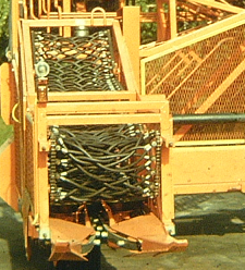
Figure 8.45 Pulling belts of a cabbage harvester
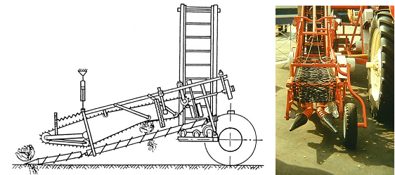
Figure 8.46 Cabbage harvester with counter-rotating helix-shaped pulling cylinders
Cleaning and selecting
In case of cabbages, cleaning means the removal of the loose external leaves. On some harvester machines the cabbage heads travel on a series of counter-rotating rubber rollers which tear off the leaves. For sorting by size a soft roller is used above the conveyor belt in the machine. It diverts the normal size heads and lets the small ones through which then get back to the ground.
Workers on the machine select and remove damaged cabbages.
Discharge elevator
According to experience cabbages are sensitive to impacts. Such impacts damage the cabbage internally, deteriorating the product. That is the reason why special discharging units are used on the harvesters.
The solutions for soft discharging include sinking of the discharging elevator in the trailer as much as possible to decrease the dropping height and slowing down the dropping speed of the cabbages before they drop into the bunker or trailer.
One of the operator’s tasks on the machine is to sink the elevator into optimal position.
In order to slow down the dropping speed of the cabbages before they get into the trailer, the cabbage heads get in between a conveyor belt and a rubber-net conveyor, both running at reduced speed.
Figure 8.47 shows a pulling belt type harvester machine. In the front two guiding cones (1) lift the cover leaves. The runts are caught by the two belts (2), are pulled out, and are transported into the machine. The cabbages slide on two rails (3) while the coulter bar (4) cuts the runts to uniform length. The heads are then forwarded on a conveyor belt (6) with the help of the rubber grid belt (5). Finally they are discharged (7) into a trailer.
The operator in the cabin (8) corrects the position of the harvester relative to the tractor to run exactly above the plant row and also sets the discharge position.
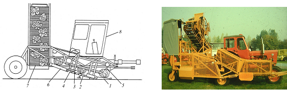
Figure 8.47 Pulling belt type harvester cabbage machine
1. gliding cones, 2. parallel belts for pulling out the roots, 3. gliding rails, 4. rotating knives for cutting the roots, 5. rubber grid belt, 6. cabbage transporting belt, 7. discharge elevator
Video 8.48 shows a one-row pull-type cabbage harvester in work.
The main data of towed cabbage harvesters is shown in Table 8.9.
Table 8.9 Technical data of two pulling type cabbage harvesters
|
Made |
MSZK–1 |
E–804/A |
|
Pulling element |
helix-shaped cylinders |
belts |
|
Rows harvested |
1 |
1 |
|
Working speed (km/h) |
2–3 |
2.5–3.5 |
|
Area output (ha/h) |
0.1–0,15 |
0.1–0.2 |
|
Mass (kg) |
2,125 |
2,100 |
|
Tractor power demand (kW) |
37 |
37 |
|
Man power demand |
1 tractor driver + 2 operator |
1 tractor driver + 1 operator |
8.3.8 Mechanical harvesting of red (chili) pepper
Although the problem of mechanical harvesting of red chili pepper is solved, the harvested area is only a small part of the growing area. The reasons for this are the following.
The mechanically harvested volume contains damaged peppers which cannot be stored naturally. It means that artificial drying is needed, which is expensive. Also post-ripening is missing which leads to lower quality of the end product.
When red peppers are near their biological ripeness they are easily detachable. By bending and pulling the pedicle the pepper breaks off.
Picking units work with the
-
combing method (reel or band)
-
breaking method (swinging rod or helix-shaped open cylinders)
Combing reel and belt
With minor conversion most of the green bean harvesters become suitable for harvesting peppers. In case of the Hungarian FZB only the combing reel must be changed. The edges of the fingers on the reel for pepper are covered by plastic knobs to reduce damages (Figure 8.49).
In the USA, experiments were carried out with combing belts and helix-shaped open cylinders (Figure 8.50). Their disadvantage is the low area performance; each unit can harvest only one row at a time.
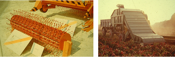
Figure 8.49 The edges of fingers on the reel in pepper harvesting
Breaking off peppers using helix-shaped open cylinders
The helixes lift the peppers periodically starting from the bottom of the plant. The sloping position ensures that breaking-off is done from the button to the top (Right in Figure 8.50).
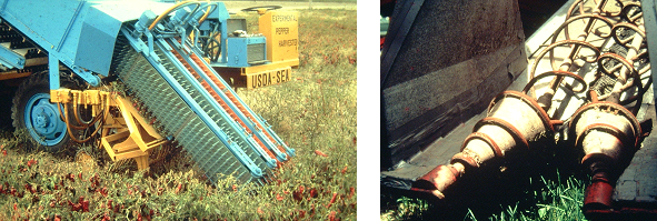
Figure 8.50 Combing belts and helix-shaped open cylinders in red chili harvesting
Mechanisation of green pepper harvesting
Green peppers are biologically unripe, so their detachment needs significant force. In Hungary experiments were run with elastic finger reels (Figure 8.51). As the harvested material contained many damaged and un-detached peppers, the attempt was considered unsuccessful.
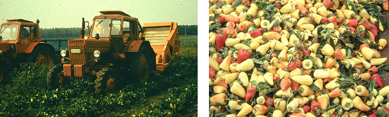
Figure 8.51 Experimental green pepper harvester and the harvested material
8.3.9 Mechanical harvesting of lettuces
Once-over mechanical harvest of lettuces is only economical, if the plantation is uniform, meaning the plants are uniform in size and thickness.
One of the one-stage lettuce harvesters is shown on Figure 8.52. A fan (1) sucks air through a rolling screen drum (2)(3) and a section of the screen drum (4). Underneath the screen drum a coulter bar (5) cuts the runts of lettuces. As a result of the sucked air, the cover leaves stick to the screen drum as long as the vacuum exists. Leaving the section of the screen drum (4) the vacuum ends and the heads are released and dropped on the conveyor (6). A rubber grid belt (7) helps in forwarding them onto the discharging unit (8). The tractor towed machine leans on the wheel (9).
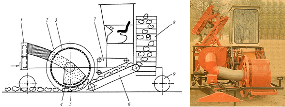
Figure 8.52 Machine in once-over harvesting of lettuces
For green leaf salads the band-sow blade cutting technology is widely used. The self-propelled machines cut the runts above ground and transport the whole bed into the machine where the plants will be put into crates or boxes or discharged on a transport vehicle (Figure 8.53).
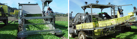
Figure 8.53 Front and rear view of a green leaf salad harvester machine
8.4 Harvesting selectively
Attempts were made to harvest, among other vegetables, lettuces selectively. The parameter for selective harvesting was either the size or the thickness of the heads. According to these, the selective harvesting tools were
-
mechanical sensor units, or
-
Gamma or X-ray sensors.
In addition to selecting the right lettuce heads, a special solution is needed for selective cutting and lifting. One possible solution is shown on Figure 8.54. It consists of a
-
mechanical sensor, (2) coulter bar which cuts only the appropriate heads, (3) pair of elastic spoke discs which turns synchronously with the forward movement. It catches only the cut heads and lifts them, (4) the head releaser mechanism frees the lettuces and lets them fall on the discharging belt (5).
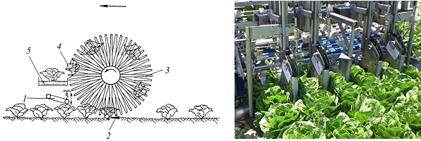
Figure 8.54 Selective lettuce harvesters, one with a mechanical (left), one with an X-ray sensor
8.5 Robots in the harvest of horticultural products
Electronics are widely used also in the harvesting technologies of horticultural products.
Many projects deal with the automation of harvesting, using robotics. Unlike in industries where industrial robots are used, in horticulture robots have to detach moving (swinging due to the wind) products with different colours at changing illumination and weather conditions.
In fruit harvesting there are already robots available for harvesting apple and oranges. Although they are performing well, for economic reasons, it will still take considerable time until their use becomes wide spread.
There are robots in harvesting greenhouse products, like tomato, pepper, cucumber, strawberry, and also mushroom. Because of the product concentration and the homogeneity of working area, the use of robots is more economical.
In most cases, the working principle is based on image processing. The main steps carried out by the robots are as follows:
-
a video camera scans the working area and stores the pictures made,
-
digitising the pictures pixels can be achieved with colour and saturation information,
-
using image-segmentation techniques, clusters of pixels with uniform information are created,
-
decision is made according to the size and/or colour of the clusters whether they can be regarded as a product to harvest,
-
for the purpose of identifying the location of a product, its x,y and z coordinates are calculated, and
-
processing the coordinates the actuator of the robot picks the product
To enable harvesting with robots, in most cases the production system must be adapted to it. Figure 8.55 shows a robot harvester for strawberry as well as the growing system of the plant.
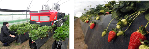
Figure 8.55 Robot in harvesting strawberries
Bibliography:
-
Mészáros F. (1984): A zöldségbetakarítás és előfeldolgozás gépesítése. Mezőgazdasági Kiadó, 272 p.
-
Láng Z., 1982. Termés-szedőujj kölcsönhatás a fésüléses betakarítás során. Járművek, Mezőgazdasági Gépek 29(8) 293-296.
-
Láng Z., 1986. Főbb elvek a paradicsom fésülő rendszerű leválasztó szerkezetének méretezéséhez. Járművek, Mezőgazdasági Gépek, 33(2) 41-46.
-
Láng Z., 1984. Szedőszerkezet a paradicsom és zöldpaprika energiatakarékos betakarításához. Kandidátusi értekezés, 116 p. Akadémiai Könyvtár.
-
Láng Z. et al., 1999. A zöldség-, dísznövény- és szaporítóanyag-termesztés berendezései és gépei. Mezőgazda kiadó,384
-
Láng Z. 2003. Betakarítógépek in: Géptan, szerk. Szendrő P., Mezőgazda Kiadó, Budapest, 452-469
![]()
![]()

Hírek/News
Sajtóközlemény
A projekt célja magyar és angol nyelvű digitális tananyagok fejlesztése a Budapesti Corvinus Egyetem Kertészettudományi Karának hét tanszékén. Az összesen 14 tananyag (hét magyar, hét angol) a kertészmérnök Msc szak és a multiple degree képzés keretében kerül felhasználásra. A digitális tartalmak az Egyetem e-learning keretrendszerével kompatibilis formában készülnek el.
BővebbenSikeres pályázat
A projekt célja magyar és angol nyelvű digitális tananyagok fejlesztése a Budapesti Corvinus Egyetem Kertészettudományi Karának hét tanszékén. Az összesen 14 tananyag (hét magyar, hét angol) a kertészmérnök Msc szak és a multiple degree képzés keretében kerül felhasználásra. A digitális tartalmak az Egyetem e-learning keretrendszerével kompatibilis formában készülnek el.
A tananyagok az Új Széchenyi Terv Társadalmi Megújulás Operatív Program támogatásával készülnek.
TÁMOP-4.1.2.A/1-11/1-2011-0028
Félidő
A pályázat felidejére elkészültek a lektorált tananyagok, amelyek feltöltése folyamatban van.
![]() TÁMOP-4.1.2.A/1-11/1-2011-0028
TÁMOP-4.1.2.A/1-11/1-2011-0028