Dimensioning and selecting modern irrigation systems
4. Dimensioning and selecting modern irrigation systems
The task of an irrigation system is to lift, deliver, distribute, and discharge irrigation water. In order to accelerate static water to the appropriate (flow) velocity (hc: velocity height), the geodesic level difference (hg: geodesic height), and the resistance resulting from pipe friction (hv: loss height) must be overcome and the appropriate operating pressure (hp: pressure height) must be ensured.
In order to achieve the above listed goals, irrigation water must have appropriate hydraulic parameters to be described in detail in the following chapter, together with several important topics of flow dynamics.
4.1. Characteristics and basic correlations in flow dynamics
-
Volume flow : the volume flowing across a certain cross-section during a certain unit of time
-
its symbol is q,
-
its (SI) unit is m³/s (for calculation, this unit is used always)
-
its other units are m³/h and l/min (used in practice)
-
Pressure : compressing force on a unit of surface, its symbol is [N/m2]. In pipelines, in most of the cases the pressure difference causes the liquid to flow.
-
Static pressure: its symbol is pst. In the case the volume flow is 0, static pressure still can be present in the pipeline.
-
Dynamic pressure: its symbol is pdin, there is flow, and it designates a pressure value related to a given volume flow.
-
Its (SI) unit: Pa = (N/m²) (for calculation, the latter is used).
-
Its other unit: bar (105 Pa) (in practice, mainly this unit is used)
-
calculation of a water column’s pressure, otherwise referred to as lift height (h):
g: acceleration of gravity (m/s²)
ρ: density (kg/m³)
-
The pressure of a 10m high water column: p = h * g * ρ = 10m * 10m/s² * 1,000 kg/m³ = 105 N/m² = 105 Pa = 1 bar
-
The pump is selected on the basis of a character curve where changes in the lift height may be observed as a function of the volume flow.
-
Hydraulic performance : Ph = q * h * g * ρ (W)
-
The pump’s efficiency :
Pm: performance of the driving motor (W)
The law of Bernoulli
In a closed pipeline, the sum of static, kinetic, and pressure energy of the flowing liquid is always constant on any cross-section, provided the conditions are ideal (meaning friction does not hinder the flow, external energy is not added or removed). This is Bernoulli’s law on conservation of energy related to flowing material.
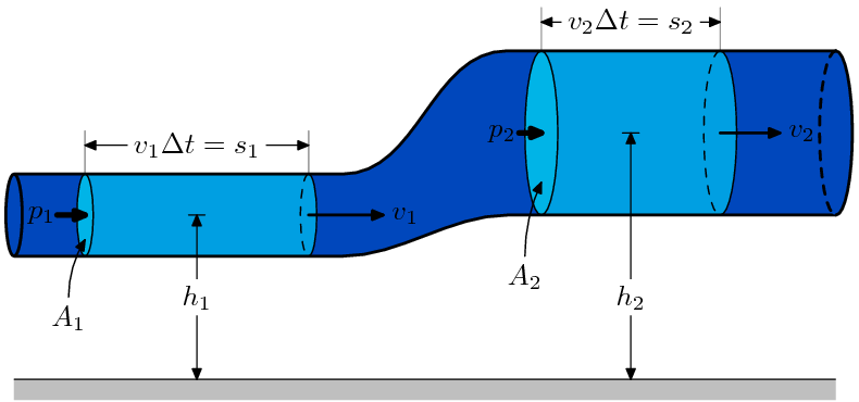
Figure 4.1 Energy changes on given sections of the network
Let us look at one part of the network (Figure 4.1):
Eö = Eh + Em + Ep = CONSTANT
Eö: total energy
Eh: static energy [J]
Em: kinetic energy [J]
Ep: pressure energy [J]
Let us note the equation for cross-sections 1 and 2:
As opposed to cross-section 1, in cross-section 2 the static energy and the pressure energy increase at the expense of the kinetic energy. We can state in general that:
dividing the equation by a unit force of gravity ():
where
h = geodesic height (m)
velocity height (m)
pressure height (m)
The Bernoulli equation is used for determining the total lift height of the pump. If the conditions are not ideal anymore, the value of the loss height (h v) resulting from friction must also be taken into consideration.
The value of hc is negligible.
The value of the loss height:
λ : internal friction factor of the pipeline
le : equivalent pipe length [m] : the correlation applies to a straight pipe section. Its value increased by 25% also includes the flow loss of the connecting profiles and the fittings.
d : internal pipe diameter [m]
q : volume flow [m3/s]
The hö value calculated from the above equation is the total lift height related to the given (qsz) volume flow of the pump. Thus, we can determine the pump’s operating point:
.
M[hö ; qsz]
4.2. The usual structure of an irrigation system (Figure 4.2)
-
Water source
-
Water lifting facility
-
Distribution network
-
Water feeders
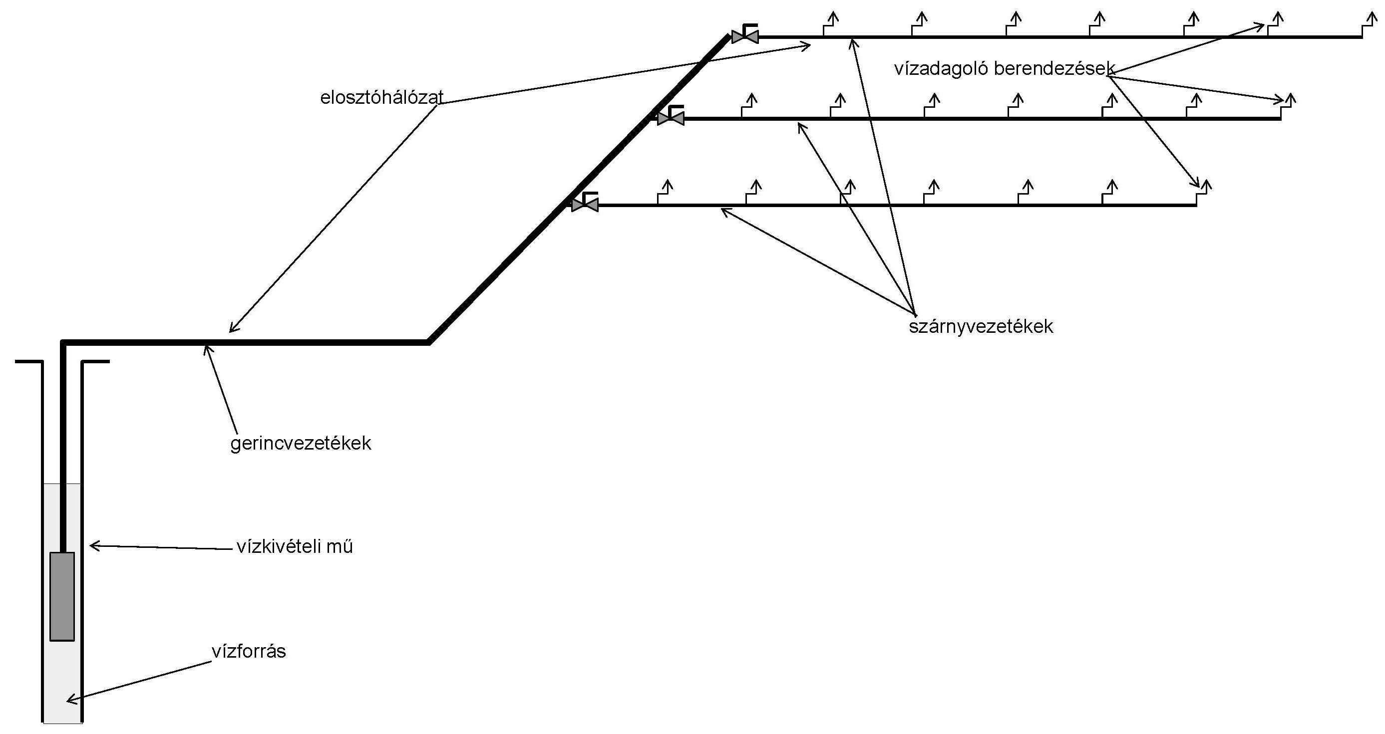
Figure 4.2 Structure of an irrigation system
4.2.1 Water source
Its task is to provide irrigation water.
Public utility network:
-
It is the most obvious solution. If the volume flow and the related operating pressure are appropriate, there is no need for further mechanical engineering investment.
-
The water does not require further treatment.
-
It is expensive. The current average price is 244HUF/m3. If there is no separate water meter installed for irrigation, then also a sewage fee must be paid, the price of which is 424HUF/m3.
-
If the incoming water quantity is enough, but the pressure is low, we can achieve the desired value by installing a pressure booster pump. The pump must be selected carefully. The value of the delivered volume flow must not exceed 80% of the value of the freely flowing water otherwise the network could absorb it. At the same time, it must ensure the desired operating pressure.
-
If the incoming water quantity is not enough, then a storage tank will be necessary. The tank must be supplied with network water at a low volume flow, and a high pressure pump will take the water from the tank. The volume of the tank must equal at least the volume of the daily water discharge.
-
If the irrigation network is connected to the public utility network, a spring loaded back-flow preventer must be installed for preventing irrigation water from flowing into the network.
Natural water :
Surface water: lake, reservoir, canals, river, stream, etc.
-
For irrigating arable land, water is obtained by using a suction pipe equipped with a foot valve and a filter basket placed under the water surface.
-
For irrigating smaller surfaces, primarily grass, water is taken from a shore-filtered dug or driven well. In this instance, the natural filter layer (pebbles, sand bed) between the water source and the well ensures appropriate straining.
Under surface : soil water, layer-water
It comes from dug or driven wells. Only surface water or water above the first water-sealing layer, namely soil water is allowed for irrigation. The quantity of the soil water constantly changes depending on the amount of precipitation and the weather. It is heavily polluted.
In case of water sources above or below the surface, water yield is the most important parameter. If the yield is appropriate, irrigation water can be obtained directly from this source. If however the water yield is low, a storage tank must be built. A smaller capacity pump lifts the water from the well and fills the tank. Finally, an irrigation pump delivers the water from the tank to the irrigation system. The volume of the storage tank must equal at least the volume of the daily water discharge.
A few related terms:
-
Static water level: the water level in dug or driven wells when there is no water removal.
-
Operating water level: water level in dug or driven wells when water is taken.
Precipitation water : this is the best quality irrigation water. However, it is investment intensive, as a reservoir and a pump system must be installed. The question arises how much time is needed for achieving return on investment. We can obtain only 6-7% of the required quantity from this source. Therefore, it is not profitable.
Technological water : by-product of some technology, for example, in case of swimming pools, it is the water delivered to the sewage system, or water resulting from some other technology, for example, cooling water.
When using natural (except precipitation water) or technological water sources, irrigation water must be tested in all cases.
4.2.2 Water lifting facility (Figure 4.3)
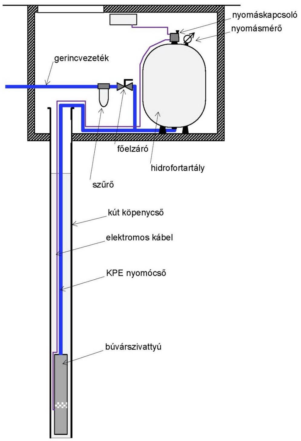
Figure 4.3 Water lifting facility
It consists of the following elements:
-
Pump which provides irrigation water with the appropriate parameters (pressure, volume flow).
-
Fittings which ensure the adequate operation of the pump (hydrofor tank, on-off fittings, filters, and electronic fittings necessary for operation).
Basically, two types of pumps are used: self-priming and submersible pumps.
Their use is determined by the depth of well’s operating water level.
-
What is the depth from which the self-priming pump can theoretically lift water?
-
The pump can lift water theoretically from a depth of 10m. In practice, it can lift water from a depth of 5-6m.
-
If the operating water level is more than 6m below the suction stub, both the self-priming and the submersible pumps can be used. If it is even lower, only the submersible pump can be applied.
Self-priming pump (Figure 4.4)
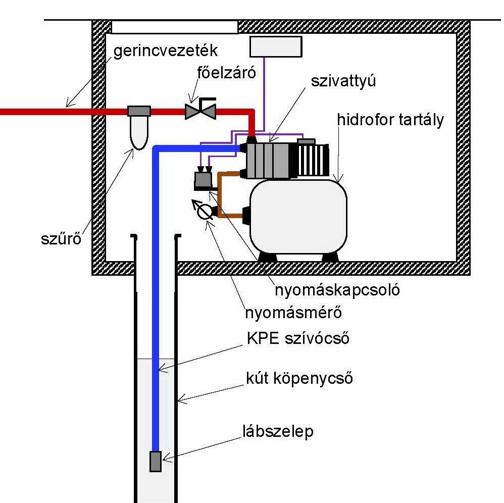
Figure 4.4 Engineering design of the self-priming pump
The pump placed above the operating water level lifts the water with a suction pipe. A spring loaded foot valve equipped with a filter is fixed to the end of the suction pipe. Its task is to retain the water in the suction pipe after the pump has stopped operating. The pump attaches to the irrigation system through its pressing stub.
Submersible pump : (Figure 4.3)
It is a pump placed below the operating water level, connecting to the irrigation system with its pressing stub. Its operation is simpler, because a suction pipe is not necessary.
Fittings of water lifting facilities :
-
Foot valve : spring loaded back-flow preventer which prevents the pump from dropping the water in the suction pipe. Its filtering function is important, because, as a result of pollution, the valve plate could get caught and drop the water.
-
On-off fittings :
-
Taps
-
Valves
-
Bolts
-
Hydrofor tank : depending on the size of the system and the lift height of the pump, it comes in 10-16bar versions. It ensures system flexibility. If only a small amount of water is taken, the pump does not have to be switched on; operating pressure is secured by the hydrofor tank.
-
Pressure meter (manometer)
-
Electric fittings (start relay, motor protection, protection against dry runs, pressure switch, frequency shift, flow sensor, level control, etc.).
Pump – operation of the irrigation network :
The pump can be started in several ways.
-
Direct start: in case of automatic irrigation, the start relay switches on the pump’s electric circuit and keeps it on during the irrigation cycle. The risk is however, that if one of the magnetic valves fails to open, the pump will keep working, but as no water is taken, it cannot deliver water. On the long term, this can lead to the break-down of the pump.
-
Flow sensor: it senses the flow and, upon reaching a determined pressure, it turns on the pump. If the flow stops, it switches off the pump. It also provides protection against dry runs.
-
Pressure regulator: it automatically regulates the operation of the pump between the set minimum and maximum values.
Pipe network character curve:
On the basis of hö = hg + hv + hp, we can calculate the values of “h” of the character curve as a function of the volume flow. The value of hg is a constant value independent of the volume flow. The values of hp and hv are proportional to the square of the volume flow. Therefore, the character curve is a parabola shifted upwards by hg.
Character curve of the pump: to be provided by the manufacturer.
We can see the two curves in the diagram; they intersect each other. The point where the pump works simultaneously with the pipe network is the pump’s operating point (M). Figure 4.5
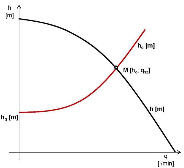
Figure 4.5 Character curve of the simultaneous operation of the pipe network and the pump
The operating parameters of pumps
The character curve shows the operating parameters. We plot the lift height and the efficiency of the pump as a function of the volume flow.
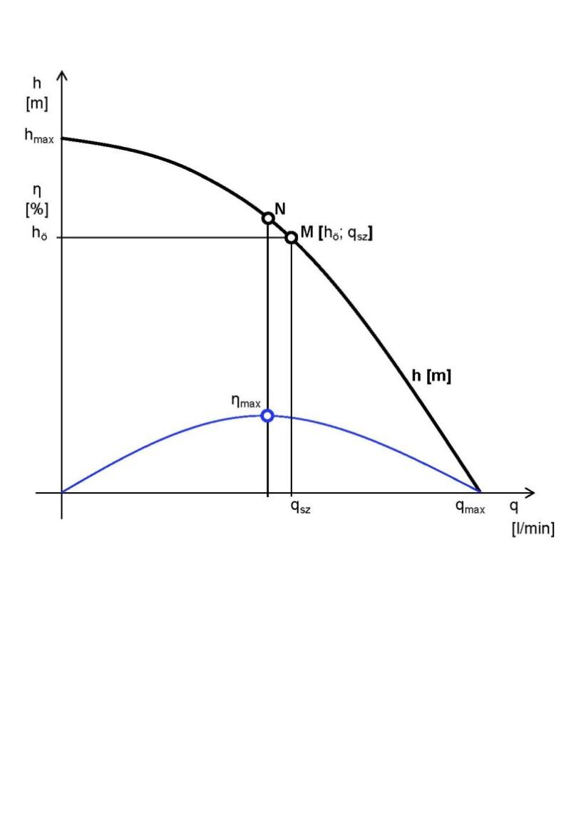
Figure 4.6 Characteristic points on the pump’s character curve
Characteristic points (Figure 4.6):
-
Maximum lift height: (the value of static pressure expressed in lift height), the volume flow is 0.
-
Maximum volume flow: (free water flow), the lift height is 0.
-
Normal point: the values of the lift height and the volume flow related to the highest efficiency. N(hN,qN)
-
Operating point: the point determined by the values of the lift height and the volume flow where the pump works simultaneously with the pipe network. The pump should be selected so that the operating point will be as close as possible to the normal point of the pump.
Operation characteristics:
-
Shell curves: curves placed on points of the same efficiency.
-
Simultaneous operation of several pumps: if (i) the water demand exceeds the volume flow of the pump or (ii) the lift height demand exceeds the total lift height of the pump, several pumps must be connected to each other. The basic rule of operating several pumps together is that only identical pumps can be connected.
-
If the goal is to increase the lift height, the two pumps must be connected in series. (Figure 4.7).
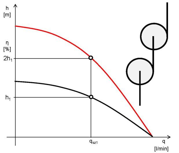
Figure 4.7 Pumps in series
-
If the goal is to increase the volume flow, then the two pumps must be connected parallel to each other (Figure 4.8).
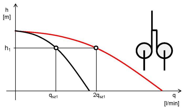
Figure 4.8 Pumps connected parallel to each other
-
If we can change the pump’s rpm, then the different hydraulic parameters will change as follows:
-
The volume flow is directly proportional to the change of the revolution number:
-
The lift height is proportional to the square of the change of the revolution number:
-
The hydraulic performance is proportional to the third power of the change of the revolution number:
4.3 Distribution network:
The distribution and delivery of the irrigation water to the water nozzles.
4.3.1 Structure:
2.3.1.1 Mainline
It delivers the water from the water lifting facility to the water distributors. They are located in the center of the irrigable area. This is where the sub-lines connect to the mainline.
2.3.1.2 Sub-line
It delivers the water from the mainline to the water nozzles. In case of spray irrigation, the sprinkler heads connect to the sub-lines with determined spacing. Considering its design, it can be stationary or mobile.
In case of a stationary design, spray irrigation is carried out by rotating sprinkler heads operating in stationary position. Water coverage is determined by the time period during which the sprinkler heads work. In terms of its location, it can be installed on the surface or built-in.
The mobile solution is based on the travelling sprinkler system. It is installed on the surface. The relocation of the travelling equipment is fully automated. It delivers water to the soil and plants while the sprinkler heads, the console or other water feeders are in constant motion. Water coverage is determined by the travel speed of the sprinkler heads or the consoles.
The water-reel travelling irrigation equipment is the most often used mobile equipment. Its main element is the 250-450m long, deformation-resistant, hard polyethylene hose. This hose determines the length and partly also the width of the strip that the sub-lines can irrigate. The hose is wound up on a drum during operation. Before starting operation, the hose is towed by a tractor to the end of the strip to be irrigated.
Figure 4.9 contains the main structural elements. With a wheel (1) and an adjustable shank (2) on a supported frame (3) the drum (4) is supplied with bearings. The hose (connecting to the water source) (5) of the equipment through a tap drives a hydro-motor (6) which rotates the drum. The axle switch, the shift gear, and an external power axle (7) drive are placed between the motor and the drive gear. The travelling sprinkler head (10) is located on a framed (8) platform (9) fixed to the outside end of the KPE hose. On Figure 4.9 this platform is in a pulled-in position, the so-called transport position.
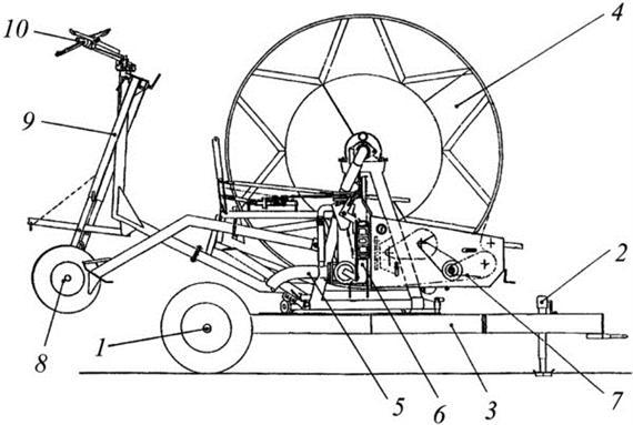
Figure 4.9 Water-reel travelling irrigation sub-line (from Janos Lelkes)
The equipment contains several automatic elements. The most important of these is the sprinkler head end-switch which turns off the water after the whole strip has been irrigated. The speed sustainer ensuring uniform water coverage in the travel direction and the automation regulating pre- and post irrigation at the beginning and at the end of the strips are also important. The so-called travelling consoles have been developed to overcome unsatisfactory work performance and energetics characteristics resulting from the wide radius of the sprinkler heads. The structure on Figure 4.10 is a pipe network (6) held by wire cords (7) mounted on a frame with a draw-bar (2, 4) running on wheels (1). The console may be installed in the place of the sprinkler head box of the water-reel travelling irrigation sub-line. The water is delivered to the pipes constituting the console wings from the KPE hose through ascending pipes (3, 5). The pulverizing (8) sprinkler heads and other types of water releasers are placed on these console wings. Using the console usually decreases the area capacity of the water-reel travelling irrigation equipment, increases relocation work, and makes it more difficult.
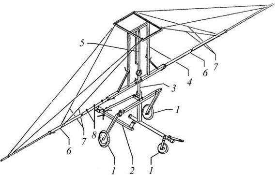
Figure 4.10 Console of water-reel travelling irrigation equipment (from Janos Lelkes)
In case of travelling sprinklers, the water coverage is:
h = qv /(B⋅v⋅1,000) [mm]
where
qv – water yield of the equipment (sprinkler head or console) [m3/h],
B – work width [m],
v – speed of travel [m/h].
-
Multi-support irrigation sub-lines:
-
Linear equipment (moving in a straight line) :
The essence of the linear equipment is that the sub-line is not on the ground but several meters above it. A platform running on wheels carries the pipe. During irrigation, the sub-line stands in a straight line (linear) and moves in a frontal direction perpendicularly to the pipe in the field. The wheels supporting the platform ensure forward travel (Figure 4.11).
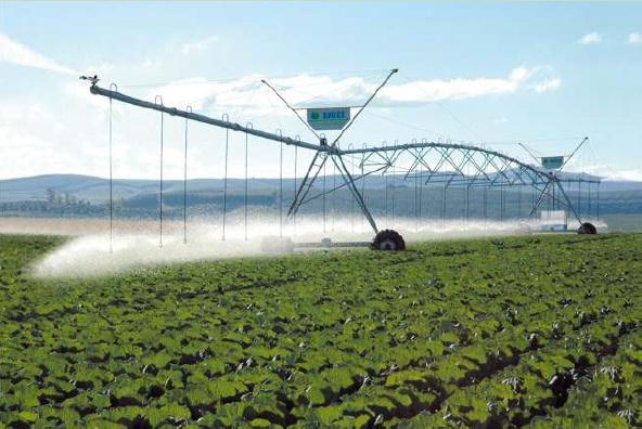
Figure 4.11 Linear irrigation equipment
The length of the sub-lines in case of supply on one side is 250-400m. The sprinkler heads can be on top of the pipe or fixed to pipes hanging down in order to be closer to the ground. Water supply is obtained from a hydrant or a canal running parallel with the travel direction. In the latter case, the equipment has a pump as well (Figure 4.12).
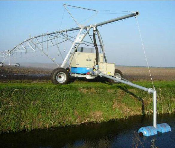
Figure 4.12 Water supply to the linear irrigation equipment
Diesel engine with 90-220 kW drive the pump and the generator. A tout wire cord, an induction cable or a guiding furrow parallel to the hydrant row keeps the pipeline in line with the travel direction. Angle deviation between the individual supports (gates) cannot be greater than permitted by the applicable regulation. The electric motor and drive gear moving the individual elements are placed on the rig. The equipment is fully automated; it does not require an operator, only periodic controls. A tractor can haul the sub-line in the direction of the pipe to the next field. The advantage of the linear spraying equipment is that it moves on the same track, thus the damage resulting from treading is minimal. Water distribution in both length and cross-wise is rather even. Consequently, the amount of water that may be used for irrigation can be well adjusted to the water requirement of the plants. Its pressure requirement is small and it is not very labor intensive. Its disadvantage arises mainly from the significant investment costs.
-
Center pivot equipment (moving in a circle) (Figure 4.13):
At one end of the pipeline is the water lifting facility (hydrant or well) serving as the center of rotation. The other members placed spoke-wise move around the center on a circular path. The outside members move with a fixed peripheral speed, while the inside members move with the automatically set speed appropriate for their distance from the center tower, keeping the pipe segments aligned. The center tower as a fixed point simplifies water supply, since it is technically easy to establish the connection to the network below the surface, or a well with a separate pump, or other above the surface water sources.
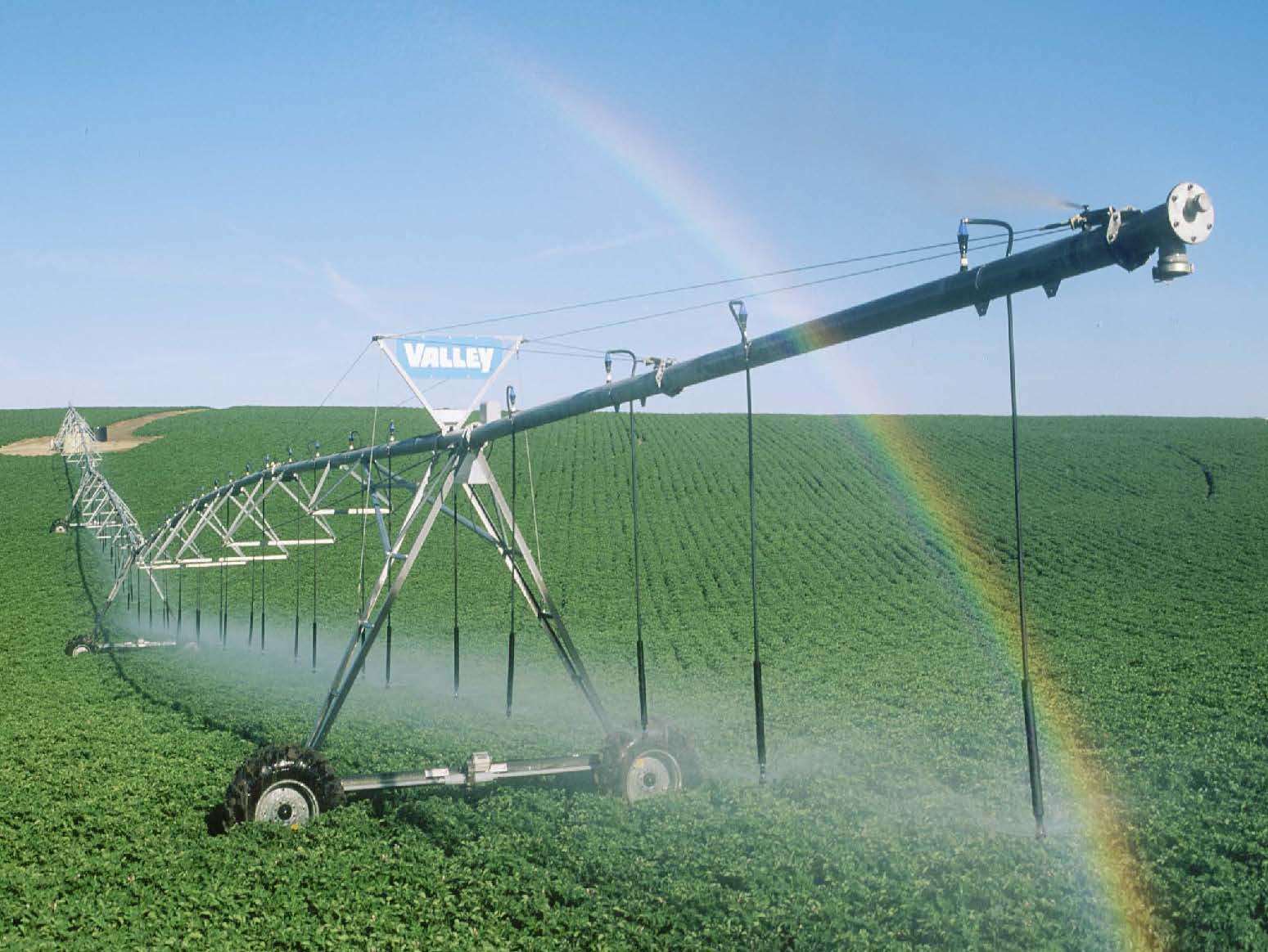
Figure 4.13 Center pivot irrigation equipment
4.3.2 Choice of irrigation system
Criteria: maintenance, cultivation, utilization, esthetics, investment, and labor requirements.
Installed on the surface : both the mainline and the sub-lines are on the surface.
-
Requires the least investment.
-
Highly labor intensive.
-
Disturbs cultivation and maintenance.
-
Relocation is done on irrigated areas (damage to the soil).
Mixed-construction : the mainline is placed under the frost limit. The sub-line on the surface connects to the mainline with hydrants inserted. The hydrants are spaced so as to meet the requirements of the given culture.
-
Requires greater investment.
-
Not as labor intensive.
-
Disturbs cultivation and maintenance less.
-
In case of manual relocation, damage is done to the soil.
Built-in : Both the mainline and the sub-lines are below the surface. Automatic sprinkler systems based on this method are built for sports facilities, public places, and formal gardens where the following criteria are important:
-
Esthetics as a result of which even the sprinkler heads are hidden. The water pressure causes the sprinkler heads to pop up and irrigate the area.
-
The utilization of the area should not be disturbed (sports, relaxation, etc.).
-
The maintenance of the area should not be disturbed (garden maintenance).
-
This system requires the greatest investment and the least labor force.
4.3.3 Parts
Pipes, jointing profiles, fittings
Pipes
Dimensions :
For metal pipes, the diameter of the pipe is given in inches. For the most often applied KPE (high density polyethylene) pipe the outside diameter is used. Table 4.1 contains the outside and inside diameters in inches.
Table 4.1 Pipe characteristics
|
Pipe characteristics |
|||||
|
Pipe sizes |
Packaging |
Pressure |
|||
|
Outside diameter |
inch |
Inside diameter (m) |
rolls |
marking |
bar |
|
D20 |
1/2” |
0.0127 |
200m |
P6 |
6 |
|
D25 |
3/2” |
0.01905 |
200m |
P10 |
10 |
|
D32 |
1” |
0.0254 |
200m |
P16 |
16 |
|
D40 |
5/4” |
0.03175 |
200m |
||
|
D50 |
6/4” |
0.0381 |
100m |
||
|
D63 |
2” |
0.0508 |
100m |
||
|
D90 |
3” |
0.0762 |
100m |
||
Characteristics : jointing profiles, pressure grading, packaging, location (under surface, on surface, closed place, manhole).
Metal pipes :
-
Aluminum, zinc-coated steel pipe, P10 pressure grade, installed in 6m strands with positive and negative pipe endings. If the irrigation equipment is installed on the surface, a Perrot quick coupler is used.
-
Soldered cupper spigots used in building engineering, but not in irrigation.
-
Threaded jointing profile made of zinc-coated steel pipe; lately GEBO steel-cast quick coupler with a grip ring is used. P20 pressure grade, installed in 2-3 strands on the surface or in a manhole. As a result of the high pressure grade, it is used for the starting mechanisms of the irrigation system. Its significant structural solidity makes them suitable for carrying bigger fittings, pumps, and hydrofor tanks.
Plastic pipes :
-
Hard PVC pipe, spigots connectible with cold welding, P6 and P10 pressure grades. It is sold in 3-6m strands. This pipe can be used above the ground, as it does not tolerate under-the-surface shifts, or in closed spaces (not UV -resistant). Although it comes with a big pipe diameter, it can be installed in small spaces. Consequently, they are used primarily in pool engineering. They are not used in irrigation.
-
High density, hard polyethylene KPE pipe used in irrigation systems. Pipe connectors:
-
Spigots in welding procedures. This is the cheaper method. The connectors can be taken apart only by destruction.
-
Quick connectors with grip ring: these can be installed later on without destroying them.
P6 and P10 pressure grades. As there is only a slight price difference between the versions, P10 can be recommended, because it meets much higher solidity requirements. It comes in 100-200m rolls; it is easy to be installed. Extension profiles are not necessary for laying down longer pipelines, if it is cut into pieces of the desired length. It is UV-resistant, but must go under the surface. Frost destroys it only if the temperature goes below minus 20 degrees; it comes with a 50 year guaranty. An example for its name is D32KPEP10. It means a high density polyethylene pipe with 10bar operating pressure with an outside diameter of 32mm (1” inside).
Pipe connectors :
Requirement: it should be solid (leak and drip free) and pressure resistant.
Quick couplers : these can be assembled and disassembled with one move.
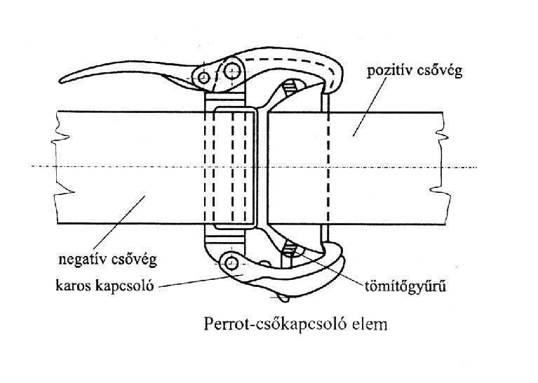
Figure 4.14 PERROT quick coupler
-
The Perrot quick coupler (Figure 4.14) is the most often applied fitting in mixed-construction distribution networks installed on the surface. The O ring ensures solidity and the appropriate position of the coupler teeth resistance to pressure.
-
The hydro-flex quick coupler is used in mixed-construction distribution networks installed on the surface.
-
Connected pipe material:
-
Aluminum, steel plate, plastic: in 6m strands with positive and negative pipe endings. It is used in irrigation systems installed on the surface.
-
Synthetic hose: serves mainly as connection between hydrants and mechanically relocated sub-lines.
-
Profiles: Cross, 450 curve, 2x450 curve, tee, Y shape.
-
On-off fittings, sprinkler heads, sprinkler head protrusion, other fittings: installed with inserts having positive and negative pipe endings.
-
-
Bayonet-joint: connecting sprinkler heads and sprinkler head risers.
Threaded profiles : with inch thread
-
Solidity, sealing material
-
Cupper profiles: Teflon tape, HILTI tape
-
Zinc-coated profiles: conical design. It is recommended to use junk and tallow. The junk swells because of the water, and the original dripping, if any, will quickly stop and will not leak even after moving the connecting profile.
-
Plastic profiles: Teflon tape
-
When fixing zinc-coated profiles with plastic profiles, we can use only Teflon tapes, as the junk pries open the plastic part (for example, the inside thread of the magnetic valve).
KPE quick connector (Figure 4.15):
-
Spigot with crimp ring for connecting KPE pipe, elbow, tee, extension, etc.
-
Threaded spigot: for connecting KPE pipe and threaded fittings (magnetic valve).
-
Pressure grade: P10, P16.
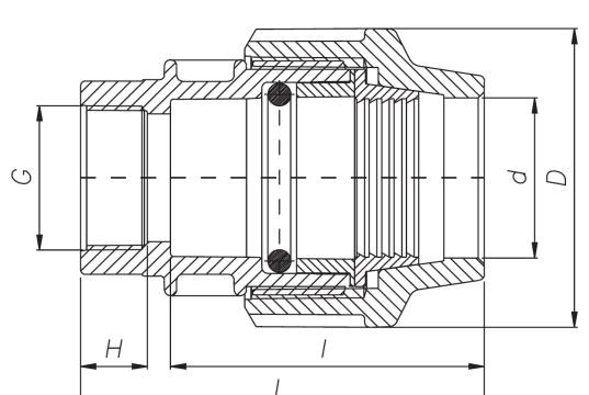
Figure 4.15 KPE quick connector
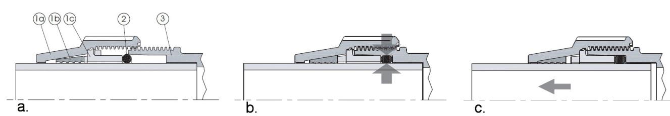
Figure 4.16 Installing the KPE quick connector
1a: Tapered nut-end
1b: Split, tapered sleeve with gullets
1c. Space retaining bushing
2: O sealing ring
3: Body of the quick connector
Its operation (Figure 4.16):
-
The O ring held in place by the bushing provides for solidity, preventing the pipe from creasing during installment. Upon pressure, the pipe pushes the tapered sleeve out, but the gullets sink into the outside surface of the pipe securing pressure resistance. The inside tapered surface of the nut-end presses the outside tapered surface of the sleeve onto the pipe in the direction of the shifting.
Fittings:
-
Back-flow preventer valve
-
Foot valve
-
Drain valve
-
Saddle profile
-
Pressure regulator
-
Manometer
-
Hydrant
-
Dividing profile
-
Magnetic valve
-
Filter
-
Nutrient solution feeder
-
On-off fittings:
-
Tap: segmenting in case of smaller pipe diameter.
-
Valve: changing the volume flow.
-
Bolt: segmenting in case of bigger pipe diameter.
4.4 Water releasers
4.4.1 Surface irrigation
In surface irrigation water moves over and across the soil, while infiltrating the soil surface. Evaporation loss is significant; this method is not wide-spread in Hungary.
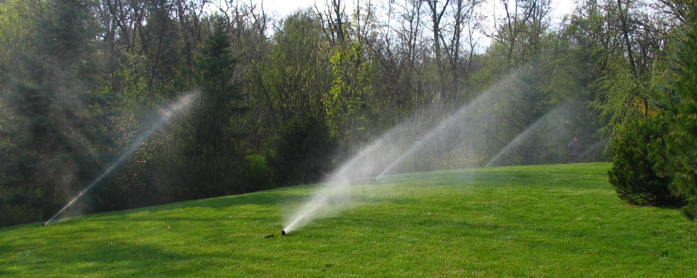
4.4.2 Spray irrigation
It is an irrigation method which imitates rainfall. The distribution network delivers the water to the sprinkler heads which shoot jets of water into the air and spread it over the soil and the plants in the form of rain drops. The characteristics of the sprinkler heads are operating pressure, volume flow, spraying radius, and cross-directional spraying uniformity. The sprinkler heads must be spaced in a square or a triangular shape depending on whether arable land cultures or grass is irrigated.
If arable land is irrigated, the goals are head-to-head coverage, meaning that is no spot should be left dry, and only a minimal overlap.
The value of water coverage in this case is:
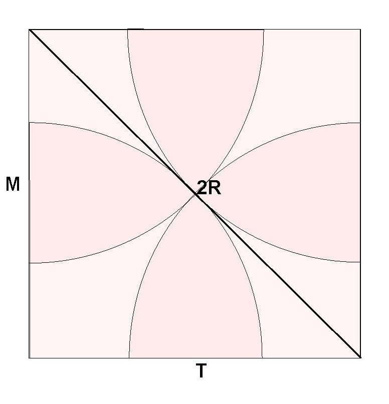
Figure 4.17 Sprinkler heads spaced in a square shape (arable land)
M: distance from the sub-line [m]
T: spacing of the sprinkler heads [m]
Asz: area covered by the sprinkler heads [m2]
Aö: area of the irrigated square [m2]
In case of grass (Figure 4.18), as a result of finer irrigation requirements, the cross-directional unevenness caused by the sprinkler heads and the distorting effect of the wind can be overcome only by ensuring appropriate overlap.
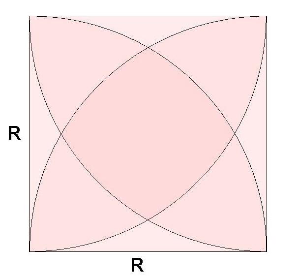
Figure 4.18 Sprinkler heads spaced in a square shape (grass)
M = R: distance from the sub-line [m]
T = R: spacing of the sprinkler heads [m]
Asz: area covered by the sprinkler heads [m2]
Aö: area of the irrigated square [m2]
The amount of water discharged by spraying and the quantity evaporated during spraying play an important role in water management. In hot weather, evaporation loss can be even 30-40%. Using automatic irrigation systems can significantly reduce this percentage, because operating at dawn, evaporation loss can be avoided.
In terms of their structure and operation, there are:
Stationary spray heads :
During operation, the spray heads do not move at all. The water jet shooting out of appropriately sized nozzles at a determined speed creates a liquid film upon hitting surface. The film gets thinner as it moves away from the point of hit and the surface pressure breaks the film into drops.
Swinging sprinkler heads :
This type got its name from the swinging motion of the water beams. The sprinkler heads have bores through which irrigation water spreads on the surface in the shape of a fan. They irrigate square shaped areas. Their geometrical dimensions may be changed by adjusting the swing gear. It is also called square sprayer. They are used for irrigating both arable land and grass.
Rotating sprinkler heads :
During irrigation, the sprinkler heads rotate. Depending on the device causing the rotating movement, we can distinguish:
Swing-gear sprinkler heads (Figure 4.19):
-
Swinging arm moving on the vertical plane
-
Swinging arm moving on the horizontal plane
Figure 4.19 Sprinkler head with swing-gear
Turbine-driven sprinkler heads (Figure 4.20):
The water entering the sprinkler heads drives a turbine which, after several cog-wheeled transmissions, rotates the sprinkler heads. The water leaving the sprinkler heads through specially designed nozzles looks like a “water curtain”. The angle of the discharge, the pressure, and the volume flow together determine the spraying radius. The correctly determined operating pressure and nozzle design result in the appropriate spray pattern (pulverization, drop size, water curtain). Higher pressure results in over-pulverization and the smaller drop size leads to bigger water runoff and evaporation. If the pressure is lower, the drop size increases, the spray distance decreases, and the spray pattern deteriorates.
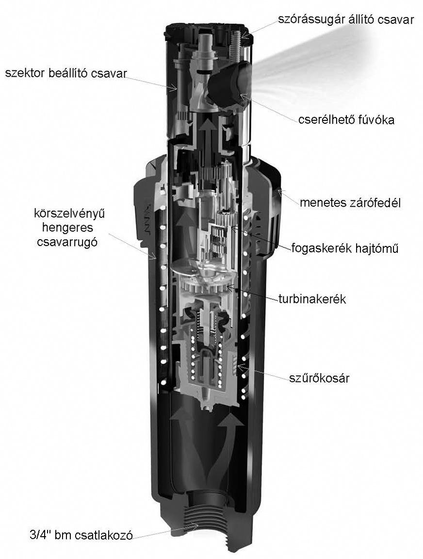
Figure 4.20 Turbine driven sprinkler heads
The sprinkler heads can spray in a range between 36o and 360o within a sector adjustable also non-gradually. Upon reaching the end of the range, the sprinkler heads change the direction of the water jet entering the turbine and also the direction of the rotation with the assistance of a flow switch.
4.4.3 Micro-irrigation
The common characteristic of the various irrigation methods used in micro-irrigation is that, at low pressure (≤ 2.5 bar) and during a unit of time, the water feeding elements discharge small amounts of water (≤ 500 l/h) to the plants. In micro-irrigation, water can be discharged in small portions, even several times a day. The goal is not to water the entire soil surface, only a determined portion of it. The most often used methods are drip irrigation and micro-spraying irrigation.
-
Drip irrigation
The water flows in a closed pipeline to the irrigation location where the water is discharged either through labyrinths (drip elements built into the pipe) or capillary tubes fixed to the pipe. With this method almost 95% of the water can be utilized; the loss is minimal. As the drip elements dissipate the water’s energy, by the time the water arrives at the nozzles, its pressure drops to the atmospheric level. On Figure 4.21, it can be observed that, while moving through a labyrinth, the water loses energy as a result of the continuous changes in direction and bumps in the drip element. As the size of the flow-through cross-section is appropriate, the drip element is not prone to clogging. Within a 1.5 - 4bar range, the amount of the water discharge is almost the same.
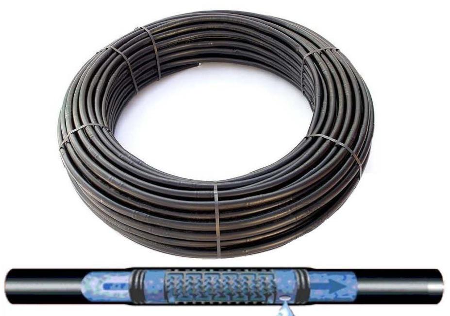
Figure 4.21 Drip pipe with a labyrinth
D6, the so-called spaghetti drip pipe, has recently come on the market. As a result of its small pipe diameter, it is suitable for watering rockeries, balcony crates and other potted plants. It requires a pressure regulator.
Drip tapes (Figure 4.22) can be used for various agricultural purposes and watering shallow-rooted fruit cultures (for example, strawberry and raspberry) and vegetables (for example, lettuce, cabbage types, celery).
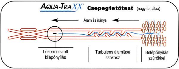
Figure 4.22 Drip tape
In case of drip irrigation, a filter with a 100-200 mesh (0.254 – 0.127mm hole-size) facing must be built in.
Drip irrigation has numerous advantages. It feeds water accurately and water loss in minimal. The drip irrigation system has many feeder elements which ensure highly uniform distribution. The system’s design ensures that water loss is insignificant and water utilization of even above 95% is easily achieved. Wind speed does not hinder irrigation nor does it influence the uniformity of distribution. Building the system under the surface is not recommended, because roots can grow into the drip elements, clogging them. Installing it on the surface is not aesthetic. However, this problem can be solved by covering it with a mulch (bark of pine trees) layer. Certain horticultural plants need relatively high humidity content which is not satisfied by the low evaporation level. In this case, misting and humidifier sprinkler heads are also needed.
-
Micro-spray irrigation
Irrigation water is delivered in closed pipelines and discharged through low intensity sprinkler heads with high pulverizing efficiency. The most often used sprinkler heads are the rotary, spray and impact sprinkler heads. Each of these types is capable of providing a circular or sector spray pattern. They overcome the problems experienced in drip irrigation such as clogging and the lack of sufficient humidity content. Further advantages are the wider rooting zones and the possibility of cooling the vegetation during the day.
Irrigation below the surface (Figure 4.23)
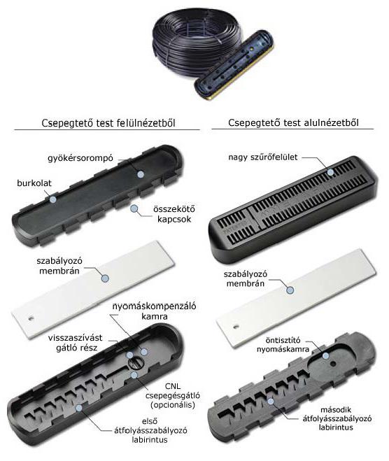
Figure 4.23 Pressure compensated, leak-free drip pipe with vacuum-breaker
Modern technology (built-in root barrier, vacuum-breaker) enables installation under the surface. This irrigation method can also be applied in irrigating slopes, since water is retained even after the operation is completed. Therefore, no puddles are left at the bottom of the slope.
As opposed to surface installation, placing the drip elements under the surface has many advantages:
-
While feeding irrigation water, there is no evaporation loss; the soil surface can be kept completely dry.
-
As there is no evaporation, soluble salts are not concentrated on the surface.
Figure 4.24 shows the water’s journey in the soil ten hours after the one-hour irrigation cycle both when the drip pipe is placed under and on the surface.
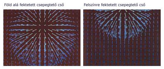
Figure 4.24 Water’s journey in drip irrigation with pipes installed under and on the surface
-
On arable land, the pipes do not have to be installed in the spring and collected again in the fall.
-
Drip pipes do not hinder work on the surface, for example, mechanical weeding.
-
The pipes are not exposed to the UV rays of the sun and the aging and decaying processes resulting from temperature fluctuations. Thus they may have a longer service life.
-
Placing the drip pipe under the surface prevents clogging caused by the roots. This new patented procedure does not harm the environment as opposed to other procedures where the drip pipes contain root poison.
4.5. Dimensioning and selecting the appropriate irrigation equipment
The procedure of dimensioning and selecting the appropriate irrigation equipment is almost the same regardless of whether the equipment is used for irrigating arable land plants (maize, vegetable, etc.), grapes and fruits, outdoor or greenhouse horticultural plants, formal gardens, sports facilities, parks, or the green surface of public places. The differences may be in the order of magnitude (water and pressure requirement), method of placement (on the surface or built-in), and discharge (spray or drip or perhaps micro-spraying) or the degree of automation.
In the following section, we will present the method of dimensioning the irrigation system to be used for watering the grass surface of a formal garden and a related tree nursery and the selection of the appropriate system by using a concrete example.
The steps that are required to be taken in planning and dimensioning the irrigation system, its selection and building are survey, data collection, planning, tender for material, purchase of material, and building.
4.5.1 Survey, data collection
Area:
In case of a new garden, the basic task is to prepare a plan. If it is an existing garden, but there is no plan, one must be prepared. The preparation of a plan requires the surveying of the area and the accurate marking on the drawing of the following items:
-
The location and the height of the existing trees, evergreens, bushes and shrubs, and grass.
-
The location of the buildings, surface coverings, garden facilities (grill, covered patio, swimming pool, etc.).
-
The orientation of various field conditions (bank, slopes, terraces, etc), the areas exposed to wind and sun, and the shaded areas.
The new garden plan must be compared to the real situation on location. Photos should be made as well, because they help during planning.
Water source
The available water sources must be examined and their location must be marked on the plan.
Public utility network :
Connection to the network should be at the closest point to the public utility network, but always near to the water meter. It is also necessary to obtain the hydraulic parameters of the water source and the characteristics and the character curve of the network. The characteristics of the network can be determined simply and quite accurately with the assistance of a pressure meter, a high pressure hose with a union nut connection, and a 10l bucket. The measuring process is conducted as follows (Figure 4.25):
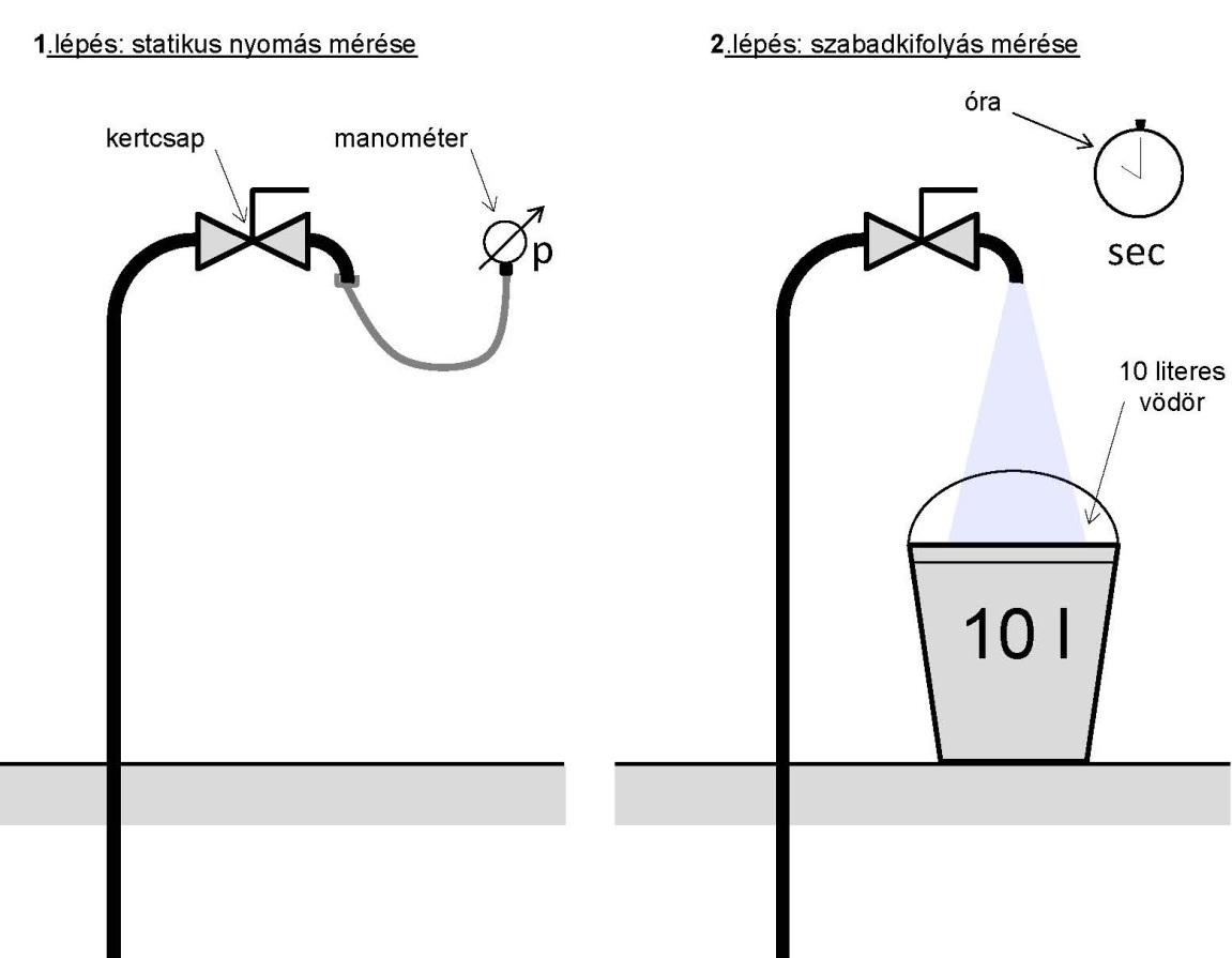
Figure 4.25 Determination of the hydraulic characteristics of a network source
1. We fix the manometer on the garden tap beside the garden water meter. When the tap is open, the manometer shows the value of static pressure (q = 0 l/min). Let us assume that the result of the measuring is 6 bar, hmax = 60m.
2. We put the bucket under the tap, open it fully, and measure the time during which the bucket is filled. Let us assume that the result is 10sec. Thus, the value of the maximum volume flow (with freely flowing water) is qmax 60 l/min. (p=0).
3. We arrive at the character curve of the network by plotting the two end points (Figure 4.26) of the character curve and connecting them to the character curve. This is naturally not as accurate as if measured with a special character measuring instrument, but it is quite accurate.
4. Finally, having obtained the estimated values of the pressure height (operating pressure) (let us assume 35m), the geodesic height (let us assume 5m), and the loss height (let us assume 5m), we can determine the location of operating point M (hö = 45m) and read the available volume flow q ö (30.2 l/min).
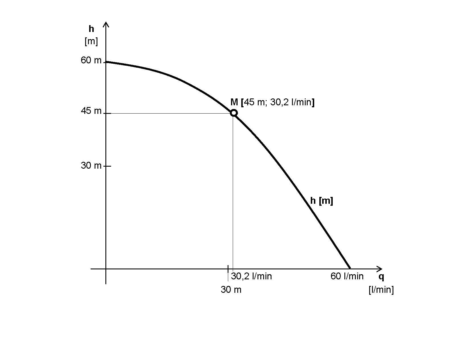
Figure 4.26 Preparation of the character curve of the network water source
Considering that water prices constantly increase, it might be worthwhile to examine the possibilities for establishing a natural water source and the time period required for achieving return on investment. We note that the energy cost of lifting 1m3 water is approximately one-tenth of the price of network water.
Natural water source :
If water is obtained from a well, the contractor digging or driving the well must provide full documentation for the well at the time of its delivery. The documentation contains, among other data, the water yield of the well. This value should serve as the basis for the dimensioning of the irrigation system. Water quality should be tested in all cases.
Location of automation: (in case of an automatic irrigation system)
Criteria: 220V supply voltage, 24V signal voltage, protection against driving rain, and it should be in the center of the area from which almost the entire irrigable area is visible.
Sensors (in case of automatic irrigation system)
Experience shows that rain sensors function with greater operation safety.
Location:
-
It should not be in the rain’s shadow (the possibility of driving rain should also be taken into account.)
-
If possible it should not be close to the plot boundary, because then it can be accessed also from the outside.
-
It should be close to the automation.
4.5.2 Planning
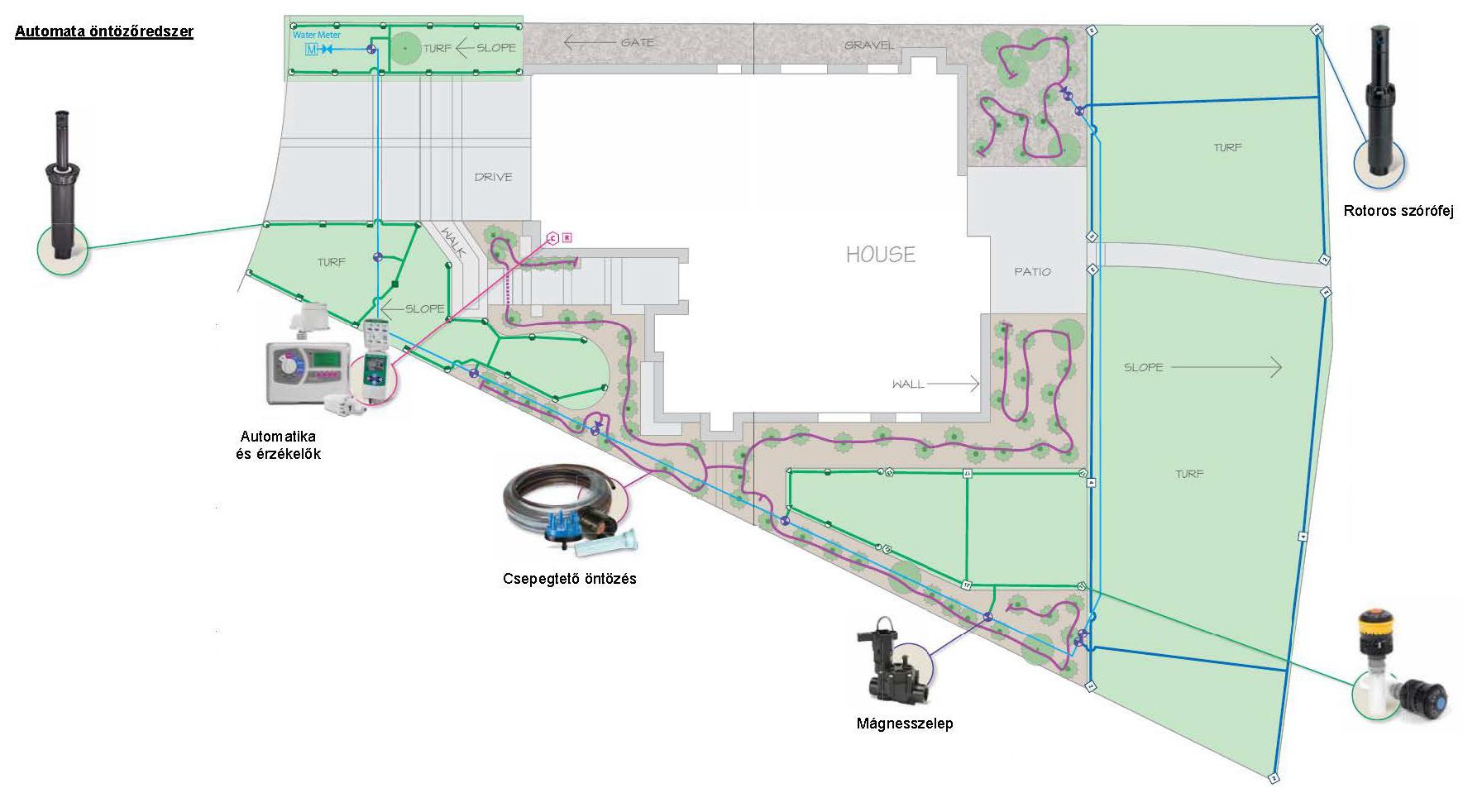
Figure 4.27 Structure of the automatic irrigation system, the drawing of the garden
Preparation of the garden plan (Figure 4.27)
Based on the survey, we draw the garden and all garden facilities proportionately to size on a millimeter paper. We can do this on a computer as well; this makes documentation easier.
Dividing the area according to irrigation methods
-
Grass: Sprinkler heads
-
Bigger, unified areas
Rotary sprinkler heads R = 6 – 12m
-
Smaller, broken-up areas
Spray sprinkler heads R = 2.4 – 5.2m
-
Tree nursery: drip irrigation
-
Drip elements embedded in a D20 LPE pipe
Spacing: 20, 33, 50, 75, 100cm. If different type of spacing is required, the equipment will have to be manufactured separately.
Water discharge of drip element: 4l/h
pü= 1.5 – 4 bar
-
Drip elements embedded in a D16 LPE pipe
Spacing: 20, 33, 50, 75, 100cm. If different type of spacing is required, the equipment will have to be manufactured separately.
Water discharge of drip element: 2l/h
pü= 1.5 – 4 bar
-
Drip elements embedded in a D6 LPE pipe
Spacing: 15cm
Water discharge of drip element: 2l/h
pü= 0.5 – 1.4 bar
-
Hedge, soil cover, evergreens: drip irrigation
-
Rockery: micro-sprinkler heads, humidifying sprinkler heads
Lawn watering
It plays an important role in the irrigation system. Its characteristics are the following:
-
It has the biggest pressure (lift height) and volume flow requirement.
-
It performs the most accurate irrigation.
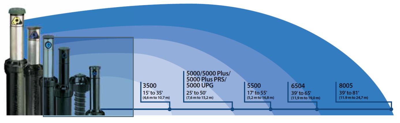
Figure 4.28 Spray range (R) of the rotary sprinkler heads
Designing the spray pattern:
Criteria to be taken into account:
-
Watering should be done from sprinkler head to sprinkler head.
-
Spray radius
-
Rotary sprinkler heads: R = 6 – 12m
-
Spray sprinkler heads: R = 2.4, 3, 3.6, 4.5, 5.2m
The spray pattern is drawn with calipers, making sure that the radius and the sector (for example, 180o, 270 o, 90o etc.) are always in accordance with the geometry of the area. The spraying radius (Figure 4.28) determines which type of rotary sprinkler heads or spray sprinkler heads is to be used.
Zone division :
Properties:
-
Available water quantity (water yield l/min)
-
Value of operating pressure, bar
Criteria to be taken into account:
-
Only the same type of sprinkler heads can be placed in one zone, because different types of sprinkler heads have different values of specific water discharge. For example, a spray sprinkler head discharges 4 times more water on a unit area than the rotary sprinkler head.
-
Choosing the nozzles of the sprinkler heads
-
In case of identical spraying radii, for example, one-fourth of the size of the nozzle watering a full circle must be built into the 90o sprinkler head to achieve identical specific water discharge.
-
If there are many sprinkler heads with the same spray pattern (for example, half circle or full circle) and they are relatively close to each other, it is worthwhile to build the sprinkler heads with the same spray pattern in the same zone.
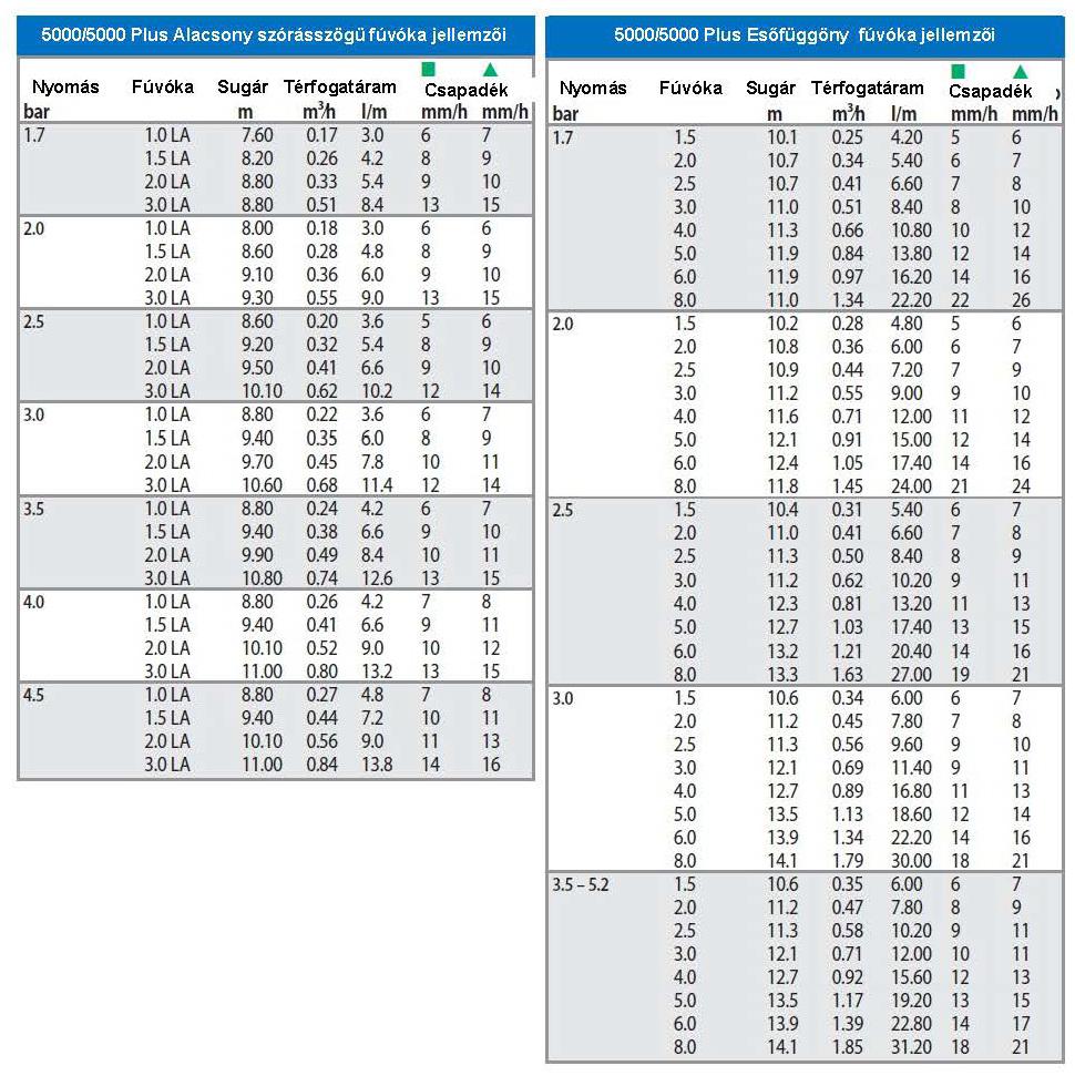
Table 4.2 Characteristic data of the 5000 sprinkler head nozzles
Zone building procedure:
-
The sprinkler heads must be numbered.
-
In the table, they are organized based on their spraying radii and spray patterns.
-
We take the volume flow based on the pressure, the spray pattern, and the spraying radius from the nozzle capacity table (Table 4.2).
-
We calculate the total volume flow (qö), then divide it by the volume flow of the water source (qk) and arrive at the number of the spray zones (Zsz). Naturally, this is not the final value, as zone division is influenced by exposure to the sun and the wind, and the sprinkler head type (rotary or spraying).
-
We designate the areas with identical exposure to sun, shadow and strong wind. We start building the sprinkler heads which are close to each other in the zones and continue until the sum of their volume flow equals the value of qö.
-
When the zone division is completed, it is possible that the volume flows of the individual zones are different.
Irrigation of the tree nursery
The simplest method of irrigating tree nurseries is using drip pipes, the spacing of which can be 20, 33, 50, 100, 150, or 170cm. If we order bigger quantities, we can decide the spacing ourselves. The most often used drip pipe is the D20 drip pipe; the water discharge of its drip elements is 4l/h.
The D16 pipe is applied in watering evergreens. The water discharge of its drip elements is 2l/h.
In case of balcony crates, potted plants, and rockeries, the D6 pipe, the so-called spaghetti drip pipe, is used. Its spacing is 15cm with a water discharge of 2l/h per each element. A pressure regulator is necessary.
Dimensioning
To facilitate better understanding, we continue our planning using a concrete example. The task is to plan the irrigation of a tree nursery and grass surface from a driven well (Figure 4.29). The tree nursery will have to be irrigated with a drip pipe with determined spacing and water discharge. Grass must be watered with spray sprinkler heads supplied with nozzles that have the water discharge and spray distance set forth in the table. A submersible pump lifts the water from a well with determined yield and operating water level. The determination of the required parameters of the pump and the operating parameters of the irrigation system constitute the last step in the planning procedure.
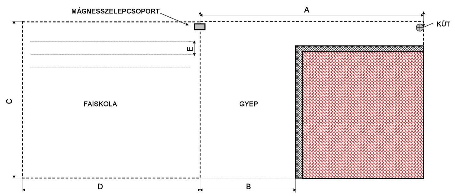
Figure 4.29 Drawing of the green surface of the garden
Data:
Distance of the well from the border of the area A 50m
Width of the grass area B 16m
Length of the grass area C 24m
Length of the tree nursery D 30m
Row distance E 1m
Stock distance S 0.5m
Water requirement of the trees M 3 l/tree/day
Water discharge of the drip element qcse 2 l/h
Spacing of the drip pipe G 0.2m
Water yield of the well qk 40 l/min
Operating water level of well hsz 7m
Pipe friction factor λ 0.02
Equivalent pipe length le 1.25 * l
where l : actual pipe length (m)
Intensity i 4mm
Criteria to be considered :
-
As a result of the different irrigation method and the specific water discharge, drip irrigation and spray irrigation may be performed in different zones.
-
The water yield of the well serves as the basis for the dimensioning.
-
The pipe diameters that may be selected: D32 or D25.
-
Requirement : the flow velocity in the pipe may not exceed (vf) 1.5 – 1.7m/s.
-
A minimum of 3.5bar is required for the appropriate functioning of the sprinkler heads. Therefore, the value of the pressure height hp should be at least 35m.
To be determined :
-
The number of sprinkler heads required for watering the grass surface. Nsz
-
The number of the spray zones. Zsz
-
The volume flow of the spray zones. qz
-
The length of the drip pipe required for irrigating the tree nursery. Lcs
-
The number of the drip zones. Zcs
-
The volume flow of the drip zones. qcs
-
The value of the pressure decrease between the pump and the sprinkler head which is farthest (the most disadvantageous position) from the pump. hv
-
The pump’s required parameters (operating point). M(hö ;qsz).
Calculations :
a. Irrigation of grass surfaces:
Determining the type of the sprinkler head :
-
The size of the area requires the use of rotary sprinkler heads. Both sides can be divided by 8, therefore, the spraying radius is 8m.
-
In the catalogue (Figure 4.28), Type 5000 rotary sprinkler meets the criteria: at a 3.5bar operating pressure, the spraying radius can be changed between 7-11m.
-
Using calipers we draw a circle or sector with an 8m radius for the area to ensure watering from sprinkler head to sprinkler head. (Figure 4.30)
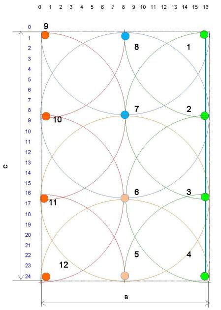
Figure 4.30 Spray pattern plan
-
Based on the spray pattern, we should select the nozzles of the individual sprinkler heads, their volume flow, the total volume flow, and the area covered by the sprinkler heads. (Table 4.3)
Table 4.3 Selection of nozzles based on the spray pattern, covered area
|
5000 sprinkler head |
R |
qf |
spray pattern |
nozzles |
total q |
area covered by sprinkler heads |
|
nozzle marking |
m |
l/m |
pieces |
l/m |
m2 |
|
|
1.5 |
8 |
6 |
quarte r circle |
4 |
24 |
201 |
|
3 |
8 |
12 |
half circle |
6 |
72 |
603 |
|
6 |
8 |
24 |
full circle |
2 |
48 |
402 |
|
total |
12 |
144 |
1,206 |
b. Number of spray irrigation zones:
On the basis of Figure 4.30 and Table 4.3 we can conclude the following:
Nsz = 12 pieces
qfö = 144 l/min
qf : nozzle volume flow [l/min]
qfö : total volume flow of nozzles [l/min]
c. Number of spray irrigation zones:
d. Volume flow of zones:
e. Construction of zones (Figure 4.31):
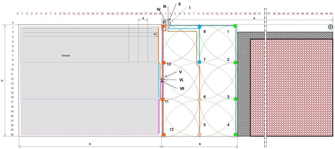
Figure 4.31 Zone division plan
Based on the zone division plan (Figure 4.31) we should put into the table the parameters of the sprinkler heads (spray pattern, nozzle, and volume flow) and the volume flow of the individual zones. (Table 4.4)
Table 4.4 Sprinkler head nozzles by zones, characteristic data
|
5000 sprinkler heads |
R |
Spray pattern |
qf |
Sprinkler head |
Total q |
qszz |
|
|
number of sprinkler heads |
M |
l/m |
pieces |
l/m |
|||
|
1, 4 |
8 |
quarte r circle |
6 |
2 |
12 |
36 |
q1z |
|
2, 3 |
half circle |
12 |
2 |
24 |
|||
|
5 |
half circle |
12 |
1 |
12 |
36 |
q2z |
|
|
6 |
full circle |
24 |
1 |
24 |
|||
|
7 |
full circle |
24 |
1 |
24 |
36 |
q3z |
|
|
8 |
half circle |
12 |
1 |
12 |
|||
|
9, 12 |
quarte r circle |
6 |
2 |
12 |
36 |
q4z |
|
|
10, 11 |
half circle |
12 |
2 |
24 |
|||
|
Total |
12 |
144 |
|||||
f. Determining the location of the magnetic valve group:
-
The “center” of the area to be irrigated can be found at the point where the tree nursery and the grass area meet, at the upper plot boundary. It contains 4 magnetic valves between zones I-IV. (Figure 4.31)
g. Determining the pipe’s cross-section:
-
We start laying down the pipe at the last sprinkler (4) and finish it at the last valve group.
-
We determine the quantity of water flowing through the sections, and from this we calculate flow velocity.
qi :volume flow on the given pipe section [m3 /s].
Ai :cross-section of the given pipe section [m2].
D25 pipe diameter - ¾” = 0.0254 * ¾ = 0.019m
D32 pipe diameter - ¾” = 0.0254m
We should calculate the volume flow at which we have to change the pipe diameter (vmax = 1.7 m/s):
-
In case of D25 diameter (below it is designated with the letter “d”)
-
In case of D32 diameter (below it is designated with the letter “D”)
-
We have to calculate the volume flow of the pipe sections of the individual zones, and based on the above criteria, we should select the diameter of the given sections (Table 4.5)
Table 4.5 Quantity of water flowing through the pipe sections of the zones, pipe diameters
|
Zone |
Volume flow flowing through the pipe section l/m |
||||
|
q1 |
q2 |
q3 |
q4 |
qg |
|
|
I. |
6 |
18 |
30 |
36 |
36 |
|
Pipe diameter |
d25 |
d25 |
D32 |
D32 |
D32 |
|
II. |
24 |
36 |
36 |
||
|
Pipe diameter |
d25 |
D32 |
D32 |
||
|
III. |
12 |
36 |
36 |
||
|
Pipe diameter |
d25 |
D32 |
D32 |
||
|
IV. |
6 |
18 |
30 |
36 |
36 |
|
Pipe diameter |
d25 |
d25 |
D32 |
D32 |
D32 |
h. Calculation of the total lift height:
The zone building plan is finished. Based on the calculations, we can now select the pipe diameters. We also have to determine the total lift height (h ö):
hg = hsz = 7m
hp = 35m
hv : to be calculated
It is advisable to reduce the constants in the equation, as it makes further calculations easier.
Constant:
We should make sure that the unit in SI is correctly applied.
Volume flow: 1l/min = 1/60,000m3 /s.
The sprinkler head in the worst position, for which the dimensioning is carried out, is the one marked 4 on Zone I.
hv = 5.6975m
hö = 7m + 5.7m + 35m
hö = 47.7m
The operating point of the pump :
M (47.7m; 36l/min)
Irrigation of the tree nursery :
The trees are watered using a drip pipe with 20cm spacing. The water discharge of the drip elements is 2l/h. We lay one row beside the tree row. Thus, the length of the drip pipes equals the length of the row.
a. Determining the location of the magnetic valve group:
The center of the irrigable area can be found at the border of the tree nursery and the grass area. It contains 3 magnetic valves between zones V and VII. (Figure 4.31)
b. The length of the drip pipe:
c. The volume flow of the drip pipe:
d. The number of the drip zones:
As the operating pressure requirement of drip irrigation is less than that of spray irrigation, 1.5bar is already sufficient. Therefore, the values calculated for the spray sprinklers are authoritative for the operating point of the pump to be selected.
Determination of the operating parameters
-
Spray sprinkler heads
Coverage of the sprinkler heads :
Size of the grass area:
The area coverage of the sprinkler heads is set forth in Table 4.3:
The value of the coverage:
Daily water requirement of the grass surface:
The operation time of the spray sprinkler heads:
The average volume flow of the zones: qz = 36l/m
Operation time of the spray zones :
Full operation time:
Operation time of one zone:
Corrected full operation time:
-
Drip irrigation:
Daily water requirement of the tree nursery (Vfi):
Total number of trees:
Water requirement:
Operation time of drip irrigation :
Average volume flow of zones: qcs = 40 l/min
Operation time of drip zones:
Full operation time:
Operation time of 1 zone:
-
Total of operating parameters :
Daily irrigation water requirement:
Total operation time of irrigation:
Control questions:
-
What does the Bernoulli equation express and for what purpose do we use it practice?
-
What are the parts of the irrigation system?
-
What kinds of water sources do you know?
-
What are the parts of the water lifting facility?
-
What is the difference between quick couplings and quick connectors?
-
What are the steps of establishing an irrigation system?
-
How do we determine the characteristics of the network water?
-
What are the planning steps in designing an irrigation system?
-
What must be taken into account in the process of zone division?
-
What is the basis of dimensioning the pipe network?
-
What are the criteria for selecting the location of the automation and the magnetic valve group?
-
What are the operating parameters to be determined as the final step in the planning process?
![]()
![]()

Hírek/News
Sajtóközlemény
A projekt célja magyar és angol nyelvű digitális tananyagok fejlesztése a Budapesti Corvinus Egyetem Kertészettudományi Karának hét tanszékén. Az összesen 14 tananyag (hét magyar, hét angol) a kertészmérnök Msc szak és a multiple degree képzés keretében kerül felhasználásra. A digitális tartalmak az Egyetem e-learning keretrendszerével kompatibilis formában készülnek el.
BővebbenSikeres pályázat
A projekt célja magyar és angol nyelvű digitális tananyagok fejlesztése a Budapesti Corvinus Egyetem Kertészettudományi Karának hét tanszékén. Az összesen 14 tananyag (hét magyar, hét angol) a kertészmérnök Msc szak és a multiple degree képzés keretében kerül felhasználásra. A digitális tartalmak az Egyetem e-learning keretrendszerével kompatibilis formában készülnek el.
A tananyagok az Új Széchenyi Terv Társadalmi Megújulás Operatív Program támogatásával készülnek.
TÁMOP-4.1.2.A/1-11/1-2011-0028
Félidő
A pályázat felidejére elkészültek a lektorált tananyagok, amelyek feltöltése folyamatban van.
![]() TÁMOP-4.1.2.A/1-11/1-2011-0028
TÁMOP-4.1.2.A/1-11/1-2011-0028