Opportunities in Plant Protection
Author: Sándor Nagy
Pest insects cause approximately 14 % loss of the yield per year on the cultivated arable lands of the world. Another 12 % of loss is due to weeds, 9 % to pathogenic fungi and viruses. Altogether approximately 35 % of the yearly crop, which means the yearly food of 1.5 billion people, is destroyed by pests. Therefore, plant protecting practices are needed in order to avoid, prevent or cure these destructive effects. The task of plant protection is to provide the demanded quantity and quality of yield at minimal costs while causing minimal pollution to the environment.
Plant protecting methods may be preventive or curative procedures. It is practical to prefer preventive ones since curative procedures only reduce the number of pests while in the case of prevention the harmful effect may be eliminated completely.
Plant protection may be:
- Edictal: in this case the prevention of harmful effects is realized by the creation of the appropriate legislation (e.g. quarantine) laws, regulations and they are in full compliance. Failing that, the American potato beetle was introduced to Europe from America (old-fashioned name: the Colorado beetle).
- Agrotechnical: this method is based on the proper selection of varieties, propagation material and crop rotation, the proper way of soil and plant cultivation, nutrition, and the optimal time and method of harvesting. Deliberate application of these procedures results in the minimum additional (marginal) cost implications.
- Biological: This method includes the increase of the number of natural enemies of pests (bacteria, predator insects etc.) in the given area or the application of biological pesticides (brew or infusion of certain plants, e. g. elder, nettle, tobacco etc.). The most effective way of biological pest control is the breeding of disease-resistant or tolerant plant varieties; however, it is a long and time consuming process.
- Physical: Basically, changing environmental conditions (temperature, light, rate of atmospheric components etc.). An example of temperature changing is the treating of seeds. In this case the number of pests adhering to the surface of seeds may be reduced effectively by heating or irradiation with electromagnetic waves. Flaming and steaming of soils are also regularly applied, though these are very energy consuming processes. Different light and food (sugary liquid) traps are also ingenious, effective and environmentally friendly controlling methods for small holdings and farms, but not really for large scale production.
- Mechanical: Injuries and deformations caused by physical force result in the destruction or the reduction in the number of pests and weeds. Manual weed control, hoeing, catching insects, scrubbing of tree trunks in spring, digging trenches for capturing locusts, then burying them with soil are good examples of mechanical pest control. Nowadays these methods are less popular because of their high demand of manual work.
- Chemical: In chemicals the effective agent can be fungicide, insecticide or herbicide. These chemicals may have preventive or curative effect depending on the way of use. Because of the multiple and multi-layer biochemical applications of these chemicals the technical requirements and specifications are also diverse. Therefore, engineering solutions and machinery selection are so diverse enabling the dispension of chemicals.
- Integrated: The aligned and complex application of the above mentioned biotechnical, cultivation etc. procedures, methods and techniques, during which the level of the use of chemicals is minimized to the lowest possible level, by which the economical loss is still tolerable. Considering the rate of the different procedures the rate of chemical control is dominating at present. However, tendencies are going toward the limitation and decrease of the use of chemicals, sometimes even to the zero point. In this case the method is called ecological farming or ecological production.
As it can be noticed from the list above, the technical toolbar of plant protection is nearly inexhaustible. As it was mentioned chemical controlling methods are dominant nowadays. Chemicals are sprayed mostly as liquid solutions or suspensions after creating drops of them. Mainly the parameters of drops determine the method of distribution, the effectiveness of control and last but not least the costs, so it is very important to study the characteristics of drops and drop production methods. On this base it is easier to select the proper spraying machine or device. Finally, at the end of this chapter the chemical-free procedures of soil disinfection are studied.
Methods of drop production, the main characteristics of drops
Chemical pesticides are distributed mainly by spraying them upon the surface.
These chemicals are usually diluted by water, and are distributed as a solution, emulsion or suspension. In an ideal situation the chemical spray covers the surface of the plant as a thin, even and smooth film, but the superficial tension ( takes a reverse effect. Therefore, sprays are distributed to the surface after dissociating the liquid into drops. In order to study the characteristics of spray cover studying the characteristics of the dissociated drops is also essential. On the base of this and taking into consideration the costs of the chosen method the right decision for the adequate and effective method of drop production may be selected.
Characteristics of drops
Diameters of the produced drops are never equal; therefore it is essential to know the drop distribution diagram, which is a feature of the drop producing method. (Figure 5.1.). On the horizontal axis the „d” drop diameter, on the vertical axis the number of the drops falling into the given range, the so called frequency can be seen. On the base of drop distribution and its situation by the horizontal axis, the methods of spraying technologies may be characterized:
- Fog production (≥ 80 % of drops are 0,05-50 μm in diameter)
- Vaporization (≥ 80 % of drops are 50-150 μm in diameter) within this range fine (d ≥ 80 % of drops are 50-80 μm in diameter), medium (d ≥ 80 % of drops are 80-120 μm in diameter) and coarse (d ≥ 80 % of drops are 120-150 μm in diameter)vaporization is defined.
- Spraying (≥ 80 % of drops are 150-750 μm in diameter) within this range fine (d ≥ 80 % of drops are 150-350 μm in diameter), medium (d ≥ 80 % of drops are 350-550 μm in diameter) and coarse (d ≥ 80 % of drops are 550-750 μm in diameter) spraying is defined.
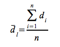
Instead of the distribution diagram of the „n” number of drops, we use the median drop diameter value that can be calculated from droplet diameters, used for the numerical characterization of the set. The median drop diameter may be calculated in different ways. The average of the „ n” number of drops is called linear median drop diameter (5.1. figure), so:
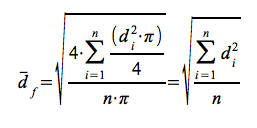
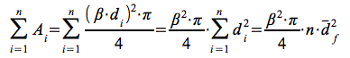
On the base of the surfaces of „n” number of drops the surface median (root-mean-square) of drop diameters can be defined:
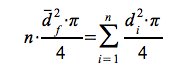
after rearrangement and reduction:
On the base of the volumes of drops the volumetric median drop diameter can be determined by the following equation after reduction:
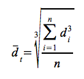
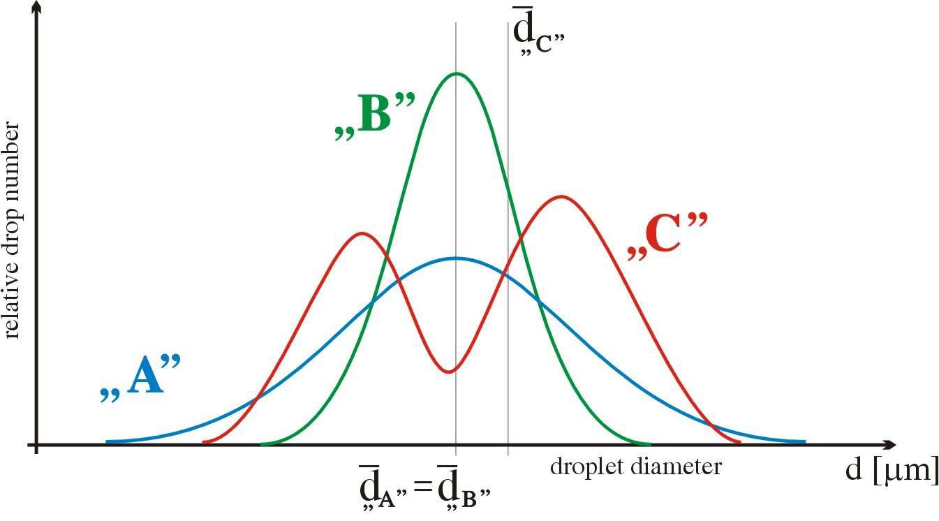
Figure 5.1. Drop distribution diagram
In case of a set of „n” number of drops ( with various diameters) the relation of the median drop diameters calculated by the above mentioned three calculating methods is:
![]()
The difference between the median drop diameters calculated in different ways is less than 1% in the case of distribution „B”, shown in figure 5.1. In less favourable cases the difference may be much bigger. In practice usually the linear average is used for the characterization of drop producing devices and machines.
If drops are hitting the surface, they wet it in a circle. The diameter of the wetted circle (A) is
![]()
where the β wetting factor. Its value is more than 1 if the liquid is wetting the surface, otherwise it is less than 1. It is better for us if β is of higher value. Since the value of β depends on the rate of surface tension it is usual that a component is added to the spray in order to decrease the surface tension. Under a certain size of drop diameter these additive components are not effective (β). The size of the wetted area in case of „n” number of drops:
 [m2]
[m2]
Taking into consideration that the number of drops that can be produced from the spray liquid volume „V” is:
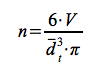
So the size of the surface wetted by a liquid volume „V” is:
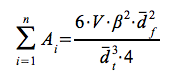
Dividing both sides of the relation by ten thousand and taking into consideration the approximation that :
![]()
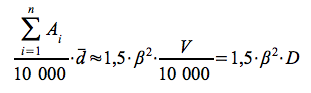
If the volume „V” is divided by 10 000, the result means the amount of spray liquid for 10 000 square meters, namely for 1 hectare. This amount is called „D” dose in practise. The value of the fractional on the left side gives the rate of the wetted area per surface. A coordinate system (chart) in which the horizontal axis shows the linear average drop diameter and the vertical axis - a logarithmic scale of base 10 – shows the wetted area per surface quotient x 100, the above mentioned relation with a given D dose can be visualized as a hyperbole. If the value of dose is 0,5; 5; 50; 150; 500 and 2.000 litre per hectare, 6 hyperboles can be drawn which divide the plane quarter into 7 parts (figure 5.2. with β=√2 ).
Figure 5.2. Nomogram of the relation between dose, cover and median drop diameter
On the base of the values shown in figure 5.2., the technologies and methods sorted by the value of dose (D):
- D≤0,5 litre/ha; in this case UULV (ultra-ultra-low-volume),
- 0,5≤D≤5 litre/ha; in this case ULV (ultra-low-volume)
- 5≤D≤50 litre/ha; in this case LV (low-volume)
- 50≤D≤150 litre/ha; in this case MV (medium-volume)
- 150≤D≤500 litre/ha; in this case HV (high-volume)
- 500≤D≤2000 litre/ha; in this case UHV (ultra-high-volume)
- over 2.000 litre (2 m3)/ha; in this case UUHV (ultra-ultra-high-volume) spraying is applied
Figure 5.2. can also be used as a nomogram for the adjustment of a spraying device or machine. The mode of action of a given pesticide determines the minimal area that is going to be covered by it in case of an effective protection. The size and developmental state of the plants determine the plant surface to be protected. In this way the value on the vertical axis of figure 5.2 can be easily determined. Counting the value of dose is also relatively easy based on the available spraying device or machine and the details of the technology mentioned above. After this, the maximal median drop diameter for which the expected characteristics exist can be defined using the nomogram. Based on this the type of drop producer with the adequate geometrical features can be selected. The minimal velocity and the minimal spraying pressure of the machine can also be determined from this relation.
In the past few years the tendency in plant protection has demanded a lower dosage of spraying and proportionately (due to reaching the required density) the decrease of drop diameter from medium to fine (except fungicides). In this way the amount of energy for transportation and drop production can be reduced while the performance of the spraying machine increases significantly. If the drop diameters are reduced, the following facts should be taken into consideration: drops are falling towards the soil surface because of their weight and the force of gravity. During this fall they can accelerate up to the speed limit of , limited by the drag. At this point the gravity force of the drops is the same value but opposite in direction to the air resistance, namely:
In which:
ρlev - the density of air [kg·m3]
ρper - the density of sprayed liquid [kg·m3]
calak - shape factor, in this case: ≈0,5
g - the value of gravitational acceleration:: ≈10 m·s2
Taking into consideration the above mentioned relation the time that is necessary for the ride between the point of drop production and the surface to be protected can be defined. Since complete doldrums are very rare the drop usually floats by the effect of horizontal winds. This is not always beneficial – it can be even harmful, for example in case of chemical weed control between the rows of plantations. Therefore, it is not practical to put the spraying frame of field machines above the level of the relevant plant height plus 1 meter.
The rate of floating may be increased also by the evaporation of the sprayed liquid. By drop production the surface confining a given unit of liquid is extremely increased. Therefore, in accordance with the increased surface the amount of evaporated liquid per time unit may also be increased. This process reduces the drop diameter continually, so the ride towards the surface is also increased. Luckily the rate of evaporation of water from the spray can be reduced if spraying is performed in the early morning or late evening hours when the humidity of the air is relatively high. In the case of ULV and UULV technologies the carrier in the solutions or suspensions is not water but a less volatile agent, e.g. Glycerine.
Figure 5.3. Device for spray characterization
In field spraying the cross directional pattern of spraying intensity of the spraying machine is needed for the selection of the proper drop producer. It can be determined for example with the spray characterizer in figure 5.3. In this device the drops emerging from the spraying nozzles are going into the tubs. The tubs are sloping towards the measuring cylinder in which the liquid is collected. Representing these values in a chart the cross directional pattern of spraying intensity diagrams shown in figure 5.4. can be obtained. In the ideal case (figure 5.4. diagram „C” ) the amount of sprayed liquid is the same in any zone (of the same width) parallel with the direction of heading, so the coverage is completely steady and uniform. The field drop producer realizing this diagram is called ideal.
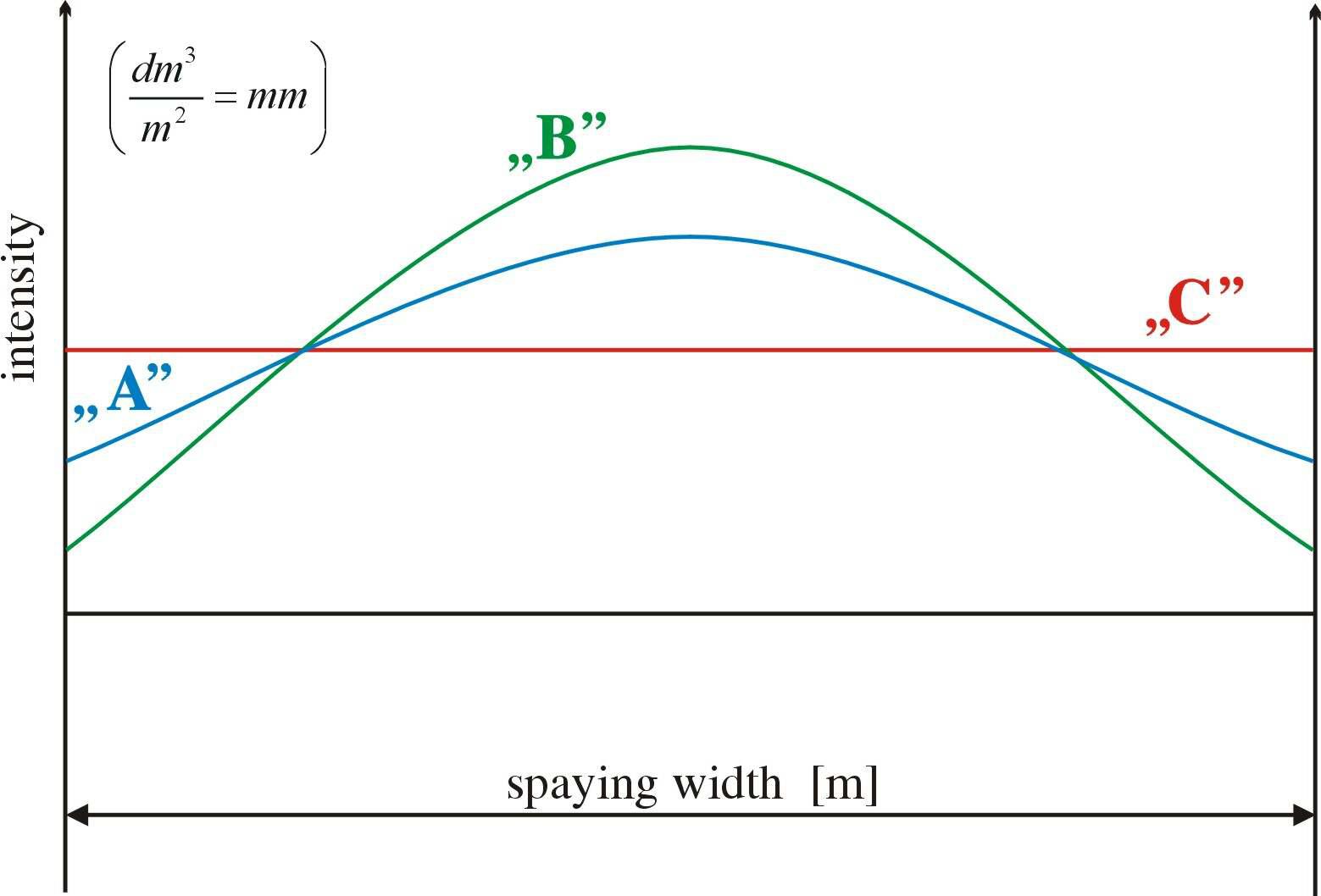
Figure 5.4. Cross directional distribution of spraying intensity
Methods for drop production
Drop production is an energy demanding process since the surface confining the given amount of liquid is increased by ΔA. The theoretical value of this energy is: E=γ·ΔA, but in practise this value is usually several times higher. Therefore, from the energetic point of view these drop producing methods are not effective. At present drop production is performed by the use of direct mechanical or electric power or heat.
Drop production by the use of mechanical power
Mechanical power is available from an inner (reduction in the pressure of liquid) or an outer source of energy. During the reduction of the pressure the surface of the cross sectional rectangle of the flow emerging from the drop producer does not change (according to the continuity principle), but the sides of this rectangle do. As one side of this rectangle increases, the other decreases proportionally. This decrease continues till the surface tension of the liquid contracts the parts of liquid into drops. The changes in the geometry of cross section of drop producers are performed by the collision or spinning of the liquid.
In case of spinning the liquid part of weight „m” moves along a straight line by speed „v” , then is forced to turn around at a point of this line in distance „r” (because of a spinning chamber of lining). In this case on the base of ![]() it gains a Π spin of which value is
it gains a Π spin of which value is ![]() , considering that
, considering that ![]() . If the liquid part of weight „m” emerges from this closed space (e. g. chamber) by an axis being normal to the plane containing r radial, and v velocity vectors, the value of velocity vki falling in line with the axis of the flow can be defined by the continuity principle. To this vki velocity vector another vectorial one is added
. If the liquid part of weight „m” emerges from this closed space (e. g. chamber) by an axis being normal to the plane containing r radial, and v velocity vectors, the value of velocity vki falling in line with the axis of the flow can be defined by the continuity principle. To this vki velocity vector another vectorial one is added ![]() . It follows from the persistence of angular momentum that when the value of rki reduces, the value of ωki increases proportionally. This can never be higher than a maximum value. Therefore, the circular cross section of the emerging flow of liquid will be a ring (with an air core). Because of the velocities of the resultant vector the liquid part with weight „m” moves along a spiral path on a conical surface. The movement of the „m” particles number „n” of the flow results in a conical, hollow spray pattern. The bevel-angle of this hollow cone depends on the angular size. The cross-sectional view of the flow (perpendicular to the axis of the spray pattern) is a ring, of which (internal, external) radius moving away from departing the closed space increases. While the difference between the two radiuses – the thickness of the ring – decreases, the liquid film thins till the surface tension of the liquid contracts the parts of liquid into drops. In case of drop producers used in plant protection the methods with a rotation lining are the most popular in which the lining can be a shell (corpus), flan (chip), or strip.
. It follows from the persistence of angular momentum that when the value of rki reduces, the value of ωki increases proportionally. This can never be higher than a maximum value. Therefore, the circular cross section of the emerging flow of liquid will be a ring (with an air core). Because of the velocities of the resultant vector the liquid part with weight „m” moves along a spiral path on a conical surface. The movement of the „m” particles number „n” of the flow results in a conical, hollow spray pattern. The bevel-angle of this hollow cone depends on the angular size. The cross-sectional view of the flow (perpendicular to the axis of the spray pattern) is a ring, of which (internal, external) radius moving away from departing the closed space increases. While the difference between the two radiuses – the thickness of the ring – decreases, the liquid film thins till the surface tension of the liquid contracts the parts of liquid into drops. In case of drop producers used in plant protection the methods with a rotation lining are the most popular in which the lining can be a shell (corpus), flan (chip), or strip.
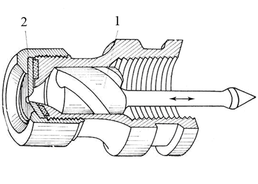
Figure 5.5. Drop producer with rotation lining
The liquid flows in a spiral path in the groove of the „1” cylindrical surface of the rotation shell (corpus) (figure 5.5.), then after crossing a calibrated hole of a flan (chip) „2” emerges into the outer space. The distance between the rotation shell (corpus) and the flan (chip) with the calibrated hole can be adjusted manually. The rotation shell (corpus) gives a spin to the flow of liquid. This spin decreases proportionally to the path to be taken as it moves turbulently toward the flan (chip). Thus, it is possible to increase or decrease indirectly the bevel-angle of the conical spray pattern (as it can be seen in the case of manual spray-guns used for spraying trees) with a handle. In case of flan (chip) (figure 5.6.) there are 1, 2, or 4 holes rotated in 90 ° from the axis of the flan (chip). In case of strip lining (rectangular, twisted along its longitudinal axis) the flow of liquid flowing along this axis gets more and more spin, depending on the distance (distance „r”) from this axis. The spray pattern is full and conical (not hollow).
In case of flan (chip) in figure 5.4. „A”, while in the case of strip „B” is the cross directional distribution of spraying intensity. Therefore, taking into consideration the ideal diagram „C”, it is not a surprise that the strip lining is not used at all, while the rotation flan (chip) lining is used only sparingly for the purposes of plant protection.
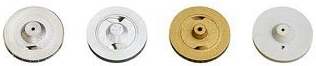
Figure 5.6. Rotation flans (chips)
The collision of the liquid flow (spray) may be:
- collision with a solid surface
- another liquid flow
- air (air vaporization)
Drop producers operating by collision with solid surfaces (figure 5.7.) are widely used in irrigation. The spray pattern of these devices is a complete circle or fan-tail (a segment of a circle). The liquid flow emerging from the drop producer moving away from the exit site considering an increased (in proportion to radius) arc (under the law of continuity) forms an increasingly thinning liquid film. The liquid film thins till the surface tension of the liquid contracts the parts of the liquid into drops.
A similar design of plant protecting drop formers was also tried. (figure 5.8.). However, these are not widespread in field use because the spray patterns easily conflict if multiple coverage is set on a field spraying frame.
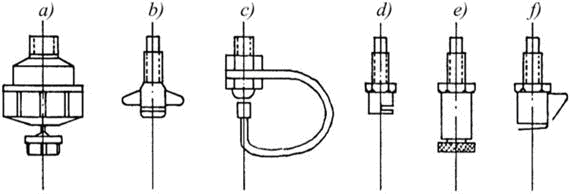
Figure 5.7. Drop producers operating by collision with solid surface
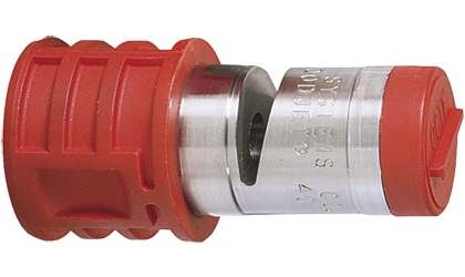
Figure 5.8. Phytosanitary drop producer operating by collision with solid surface
Drop producers operating by the collision with another liquid flow, the so called „slit” drop producers are much more important. It works by two liquid flows in the same plane but not parallel collide as shown in Figure 5.9. In this case, like in the previous one a fan shaped (circular or segment of a circle) spray pattern is created in a plain containing the bisector of the two flows and being normal to the plain of the flows. Just like in the previous case the liquid flows moving away from the drop producers create a liquid film which thins with the rate of the distance from the exit site. (on the base of the continuity principle). The liquid film thins till the surface tension of the liquid contracts the parts of liquid into drops.
The structure of the collider consists of a hemispherical calibre with an oval „slit” on its bottom through which the liquid emerges. The flow – being circular in cross section – is breaking in 90 ° in its direction when reaching the oval slit. One half of the flow (half circle in cross section) is forced to move in the opposite direction compared to the other half of the flow. Taking into consideration the „a” length of the slit, the spray pattern will be fan-shaped, namely a section of a circle with central angle φ (Figure 5.9.). Arranging this spray pattern normally to the channels of Figure 5.3. we get the cross dimensional diagram of spraying intensity shown in Figure 5.4. „C”, if the bisectors are vertical. This ideal distribution curve justifies the almost exclusive use of this drop producing method in field frames.
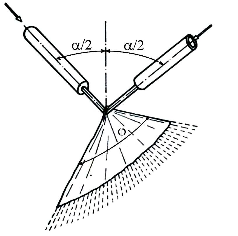
Figure 5.9. Collision of liquid flow with another flow
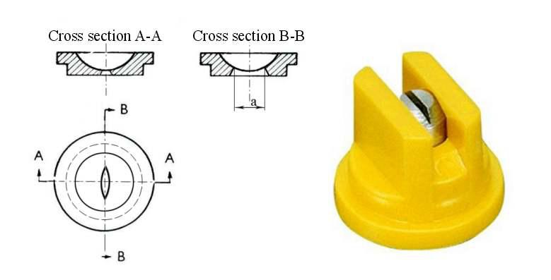
Figure 5.10. Structure of a „slit” drop producer
Methods of vaporization by the „collision” of a liquid with air flow, possibilities ofcollision with an air flow – namely vaporization – are illustrated in Figure 5.11. The figure shows the I "base" case . If the value of ![]() is increased (the difference between the velocity of air and the velocity of drops) an increasingly intensifying secondary drop refinement occurs. The value of this difference changes at a given air and liquid (drop) flow rate value depending on the position of these velocity vectors. Case I. illustrates a matching,, while case II. a countercurrent collision. Injector drop producers allow primary drop breakdown in this way (figure 5.12.). By these drops will contain air bubbles that released from a closed space are broken into smaller droplets. Another method increases the size of the interface between the air and liquid flow by changing partly the direction of the liquid flow (Figure 5. 11. case III.). In this case the complete air vaporization of the flow is performed in a shorter way. However, the practical importance of the secondary pneumatic refinement of drops is higher than this primary air vaporization method. In this case the pipeline of the sprayers put under the wings of the phytosanitary airplane can be turned around their axis. In one terminal position a matching flow (case I. of figure 5.11.), while in the other terminal position (135° turned) a countercurrent flow of case II. can be performed. By the latter option the diameter of the drops can be halved compared to that of case I. Naturally, if the drops are smaller, the value of drifting increases, so case II. should only be used and is only justified for fungicides.
is increased (the difference between the velocity of air and the velocity of drops) an increasingly intensifying secondary drop refinement occurs. The value of this difference changes at a given air and liquid (drop) flow rate value depending on the position of these velocity vectors. Case I. illustrates a matching,, while case II. a countercurrent collision. Injector drop producers allow primary drop breakdown in this way (figure 5.12.). By these drops will contain air bubbles that released from a closed space are broken into smaller droplets. Another method increases the size of the interface between the air and liquid flow by changing partly the direction of the liquid flow (Figure 5. 11. case III.). In this case the complete air vaporization of the flow is performed in a shorter way. However, the practical importance of the secondary pneumatic refinement of drops is higher than this primary air vaporization method. In this case the pipeline of the sprayers put under the wings of the phytosanitary airplane can be turned around their axis. In one terminal position a matching flow (case I. of figure 5.11.), while in the other terminal position (135° turned) a countercurrent flow of case II. can be performed. By the latter option the diameter of the drops can be halved compared to that of case I. Naturally, if the drops are smaller, the value of drifting increases, so case II. should only be used and is only justified for fungicides.
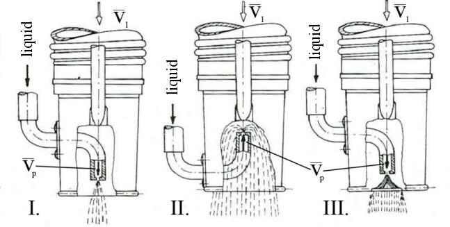
Figure 5.11. Methods for air vaporization
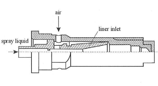
Figure 5.12 Injector drop producer
Among mechanical drop producers the rotating plate, or cone, and the liquid disruption should be mentioned.
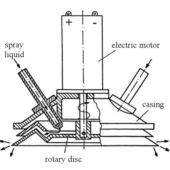
Figure 5.13. Drop producing method with a rotating plate (cone)
The liquid flow generally reaches the rotating cone (figure 5.13.), or plate through a removable calibrated “choke” either by gravity. The liquid flows in a very thin layer along the serrated edge of a D diameter rotating cone or plate usually propelled by an electric engine, of which rev is „ n” 5-15 000 per minute) . At the edge the centrifugal force secedes circumferential portions of the liquid.. Regression correlation specified for the emerging medium droplet diameter:
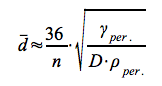 [mm]
[mm]
in which:
γper - the surface tension of the liquid [Pa·m]
ρper - the density of the liquid [kg·m-3]
n - the rev per minute of the plate or cone with diameter „D”
In order to reduce the drop size the furrowing of the edge of the rotating cone was tried but but such a configuration, resulted in the 5.2. spray pattern of the drops lagging partly from the bottom of the grooves and partly from the pole between two adjacent grooves.. It is far from the ideal diagram of figure 5.1. „B”, therefore, the furrowing of these surfaces was left.
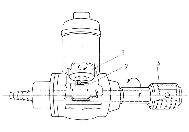
Figure 5.14. Drop production with the disruption of liquid flow
The disruption of a liquid flow can be performed for example with the device in figure 5.14. The spray in the horizontal pipe can flow out only under the part indicated by no 3, through the calibrated holes along the pipeline component. The flowing streams get through the holes of the part turning right-left (indicated with no. 3.), or do not get through them. This way the breakdown of liquid jets to parts happens.. These parts are formed into drops because of the surface tension of the liquid. The diameter of the drops may be adjusted by changing the intensity of the flow or by the modification of the frequency of moving part (3). The changing of the angle velocity of the right-left movement may generate vibration, so usually a rotating cylinder with 24 windows or slits is used instead of the part indicated with (3). In this case the rev of the cylinder may be even 15 000 per minute and the produced drops are very fine. The distribution diagram of drops can be similar to diagram „B” of figure 5.1. Therefore, this method is widely used in aerial spraying (performed by airplane or helicopter) figure 5.15.
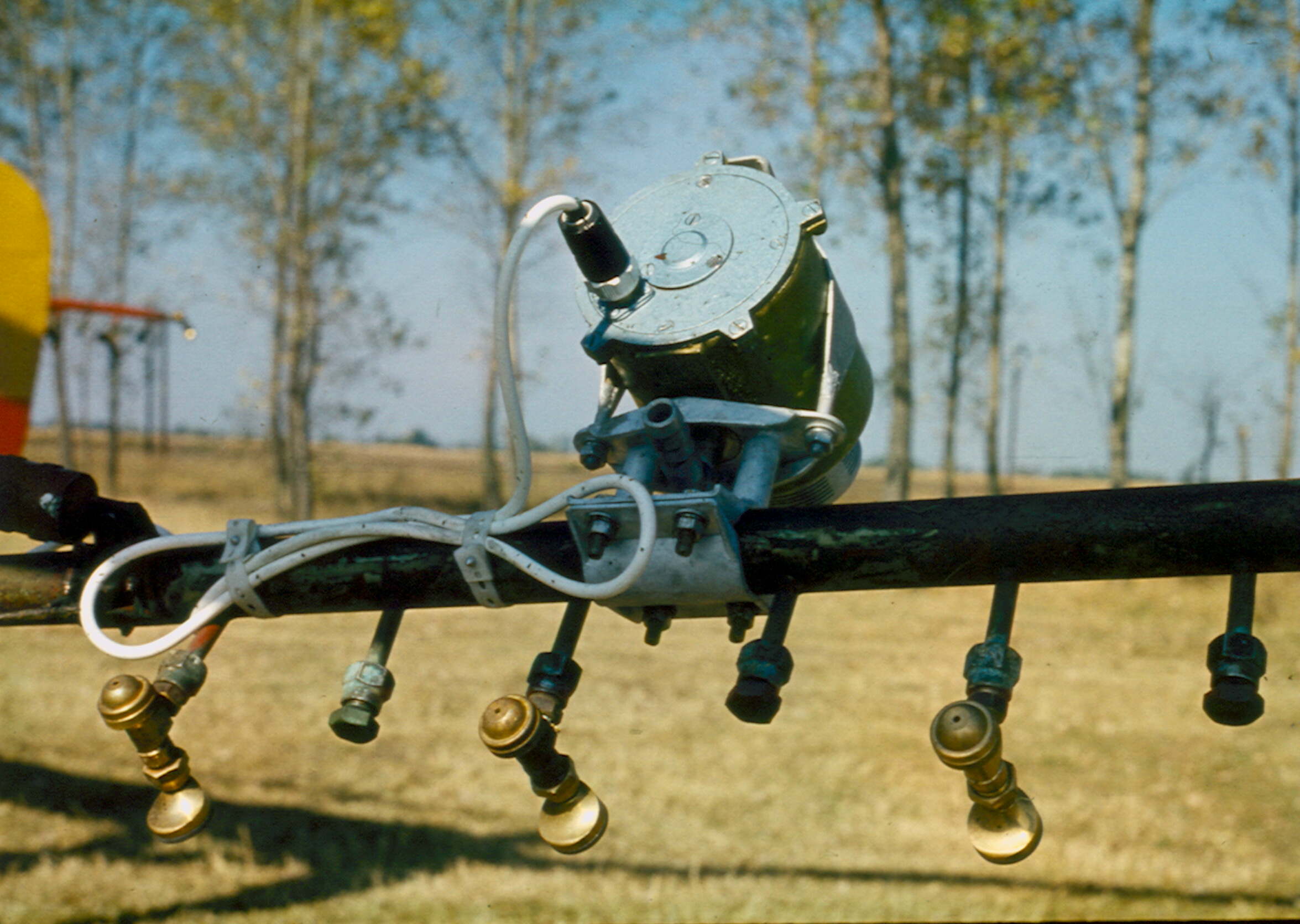
Figure 5.15. Spraying frame, on the bottom a drop producer with a rotation lining, on the upper part a drop producer with disrupting liquid flow by a rotating cylinder is connected to the pipeline.
Drop production with heat energy
Spray evaporation by thermal energy is acheived by heat (thermal) fogging (figure 5.16.) In this case gasoline is introduced into the stream of a Root-injector. Later in the combustion chamber this air-gasoline mixture is ignited by the spark of the ignition magnet, subsequently by the heat of the walls of the combustion chamber. After combustion the stack gases flow into a tuned resonator pipe in which they induce a resonation of approximately 90 Hz. The liquid chemical is injected into the fast flowing gas mixture at the end of the resonator pipe. The liquid evaporates and its steam mixes with the flowing gases. When the temperature of this mixture reduces to 100 °C, the steam condensates upon the tiny particles of the stock gases. The medial drop diameter will be under 50 m, so fog is produced. Due to the high penetration of fog this method allows fast and effective protection against insect infections in dense foliage, closed greenhouses, dense woods. However, it should be always taken into consideration that the used chemical agents should be heat resistant, stable also at high temperature.
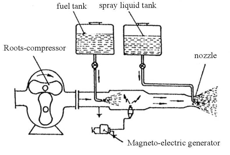
Figure 5.16. Thermic fog producer
Spraying chemicals may be mixed not only in water but in other volatile solvents as well (CCL4, acetone (CH 3)2CO, chloroform CHCl3 etc.). The per hectare costs of these solvents are not so high if ULV or UULV technologies are used. Such spray-like solvent is exposed above the protected file by a drop producer by, for example, reducing the pressure energy. After the intensive evaporation of the solvent, the diameter size of the remaining drops usually fits into the fog category. For the evaporation of the solvent, thermal energy proportional to its evaporation heat is needed. Drops obtain this energy by decreasing the inner energy of the surrounding air, its temperature. Because of this air cooling effect, this method is also called cold fog production.
Drop production by electric energy
Electric energy is used usually not primarily and directly for drop production but for creating surplus electric charge (electron or proton) in some other way produced drops. Using this method drops can be „forced” to reach the earth potential in the shortest way possible (in the air) after emerging from the drop producer. On the surface of the earth - that has almost endless electric capacity – the drop meets the missing electrons or protons and becomes neutralized. In this way drops do not drift far from the producer device, so the saving of chemical is significant (up to 15%) if compared to other methods, while the coverage (size of the wet area) remains the same. This method is called electrostatic dispersion.
Charging crown (Figure 5.17.) In this case a metal ring (crown) encloses the spray pattern of a mechanical drop producer but it does not get in touch with the emerging liquid flow. The ring has a potential of 10-15 kV with positive or negative polarity (its polarity is negative in the figure) that induces division of charge in the liquid particles within the ring-enclosed space. In the initial phase of the spraying pattern electrons can exit through the closed circuit created by the grounding of the tank (as shown in figure 5.17.) since the liquid flow is continuous. Subsequently, the liquid stream breaks into droplets and the drops can only obtain the missing electron or proton from the surface of a plant or soil on the earth potential.
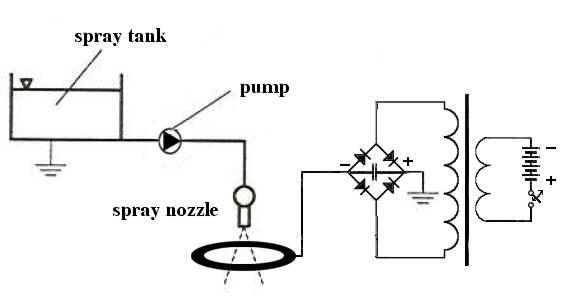
Figure 5.17. Charging crown formation
Contact charge In this case the negative pole of a direct strong current source is connected to the drop producer by a semiconductor, as shown in figure 5.18. The „ I” direct current developed by high voltage puts „Q” amount of electrons or protons (electrons in the figure) within a given time unit into the liquid flow exiting the drop producer. After that the flow thins and decomposes into drops. If an average n drops are produced within the given time unit, the average plus charge (electron) within a drop is: q=Q/n coulomb. The medial diameter of drops is determined not only by the surface tension of the liquid but also by the plus charge of electrons (or protons) because of their repulsive effect, according to the Coffé-effect:
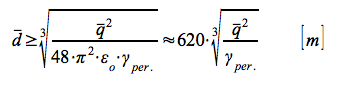
in which ε0 is the dielectric constant of vacuum.
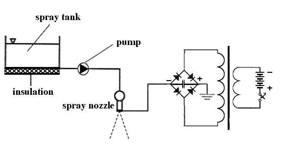
Figure 5.18. Contact charge development
Carefully studying the methods for electrostatic dispersion mentioned above we can see that these methods are not suitable for aerial spraying since the establishment of proper grounding needed by the closed current circuit is not possible.
Soil sterilization
The condition for growing vegetables and ornamental plants safely is an appropriate soil free of harmful pests and plant residues. Monocultural and repetitive growing in greenhouses favor for the proliferation of pests, thus reducing crop yields. Therefore, it is necessary to sterilize the soil regularly. This process can be done by the use of chemical agents or by heating the soil. Chemical treatment is usually specific, effective against, for example, nematodes and larvae, therefore not as effective as steaming. Heat treatment, that means steaming in phytosanitary, is a more effective way of soil sterilization. Therefore, it is useful to review this method. Increasing the temperature of soil up to 85-90 °C and keeping this temperature for at least half an hour results in a relatively sterile soil (concerning horticultural use). Higher temperature may destroy also the useful bacteria (nitrifying bacteria) and other microorganisms that are necessary in effective plant production. Heating the soil over 110 °C destroys all living organisms and the soil becomes sterile. This can be most dangerous since a few harmful pathogenic organisms getting accidentally into this sterile soil may proliferate enormously within a short time and destroy the crop. Heating can be performed on the spot or in a heap of growing medium. The usual method for heating soil is steaming (except for drum sterilizers), so this method is also called steaming.
The simplest implementation of steaming in a heap is steaming on a truck trailer. In this case one, for continuous steaming two tip-cart trailers are necessary.. At the bottom of these trailers a perforated pipeline is placed in order to distribute the steam evenly. Homogenized soil is placed upon the trailer by an excavator. Following the leveling the nearly equally thick soil layer is covered by a good insulating layer. Continuous introduction of steam into the pipelines performs the sterilization of 2-3 m3 soil within 1.5 hours. Another method is steaming with the use of a steaming grid. In this case a grid is placed upon a solid surface (usually concrete) and the soil is spread over this grid sometimes forming up to 1 m thick layer. After this the process is similar to that of steaming on a trailer. Depending on the geometry of the pipeline and the thickness of the soil layer a larger amount of soil can be steamed in one process, although the transportation and labour costs are higher than when steaming on the spot or on a trailer.
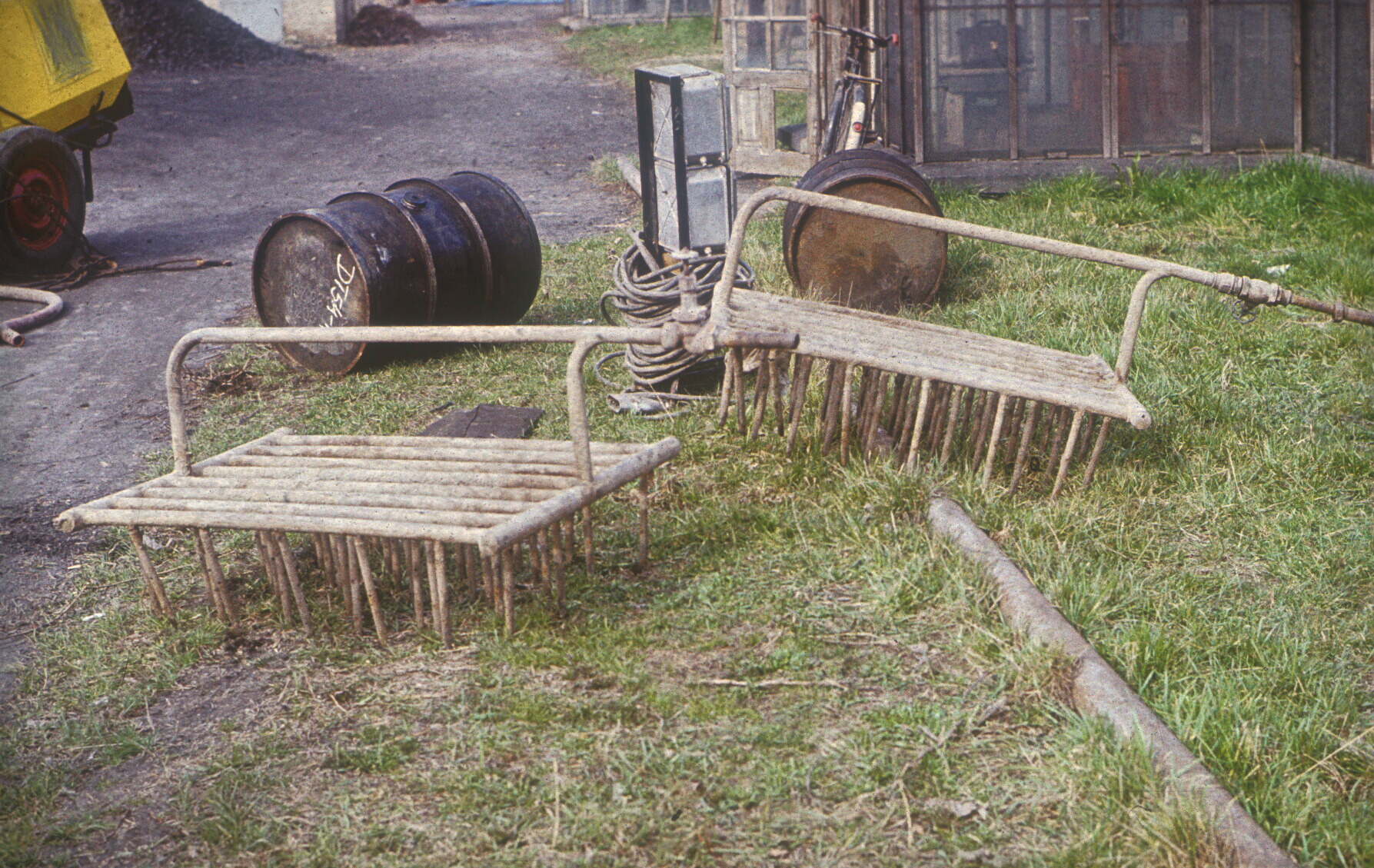
Figure 5.19. Steaming fork
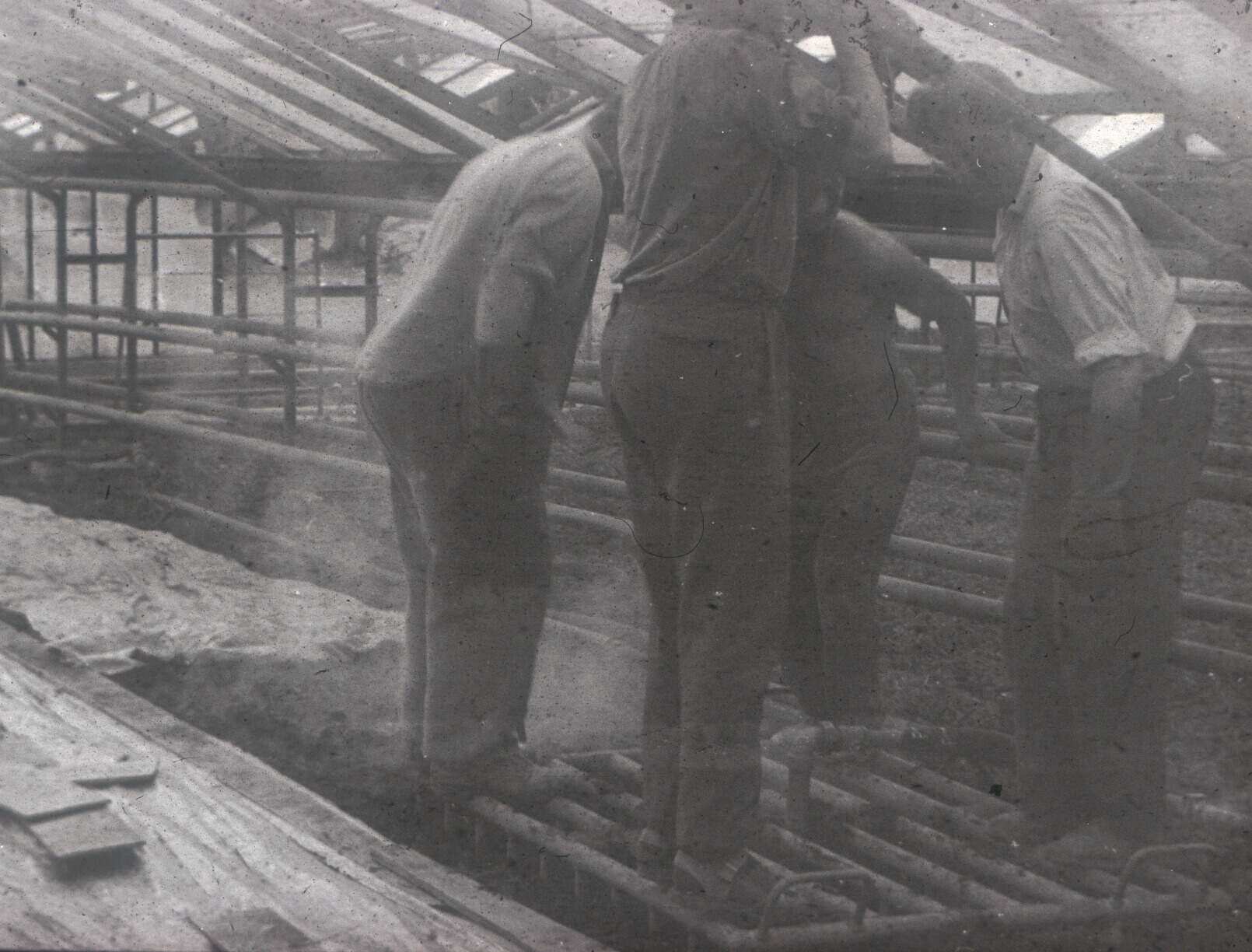
Figure 5.20. Placement of steaming fork
Steaming on the spot is performed by the use of a steaming fork (figure 5.19.). The steam distributor grid or fork is pushed or trampled into the desired depth (figure 5.20.) and then steam is introduced into the soil through the fork. Steam leaving the lower ends of mandrels and then flowing upwards in the soil continuously condenses. During this the soil temperature increases. If the temperature reaches 85 °C, the steam flow is terminated and the grid is taken off the soil. After that the steamed soil is covered by an insulating layer (plastic film + polyurethane foam tables), so the temperature is preserved for the necessary 30 minutes. Placing the grid to the next part of the soil the process is repeated. This method is no longer used in Hungary because of its high demand for manual labour and the need for careful work to avoid potential burns. Steaming plow (figure5.21.) is connected to a windlass standing at the end of the plot by a wire rope. The steam is conducted into the distributor drum of the plow by a flexible pipeline and emerges from the holes of the pipelines driven into the proper steaming depth. Similarly to the method of steaming with a grid the steam flows upwards and heats the soil by condensation. It is problematic to harmonize the proper parameters of steam flow and the velocity of pulling (adjustable on the windlass), so the soil may be easily overheated or the temperature does not reach the value needed for sterilization. Maybe this is the reason why it is unpopular in Hungary, though it was widely used outdoors in Western Europe.
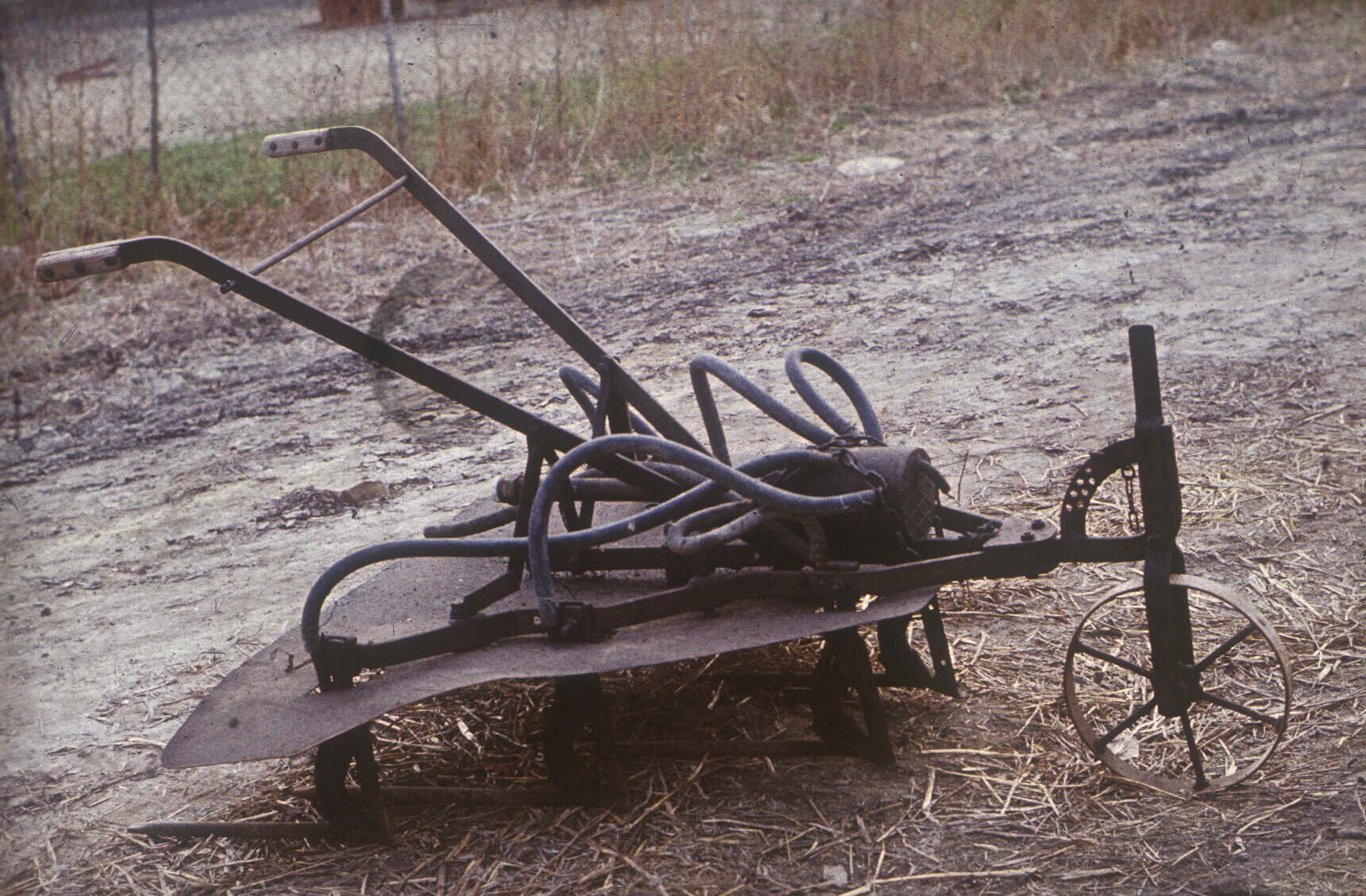
Figure 5.21. Steaming plow
In Hungary the need for steaming in the spot arises mostly in producer plants currently. There are two methods for steaming in greenhouses. One of these is establishing a network made of terracotta pipelines in the depth of 50-60 cm (BEDU system). This system can be used for irrigation, soil heating and also for soil steaming. Empirical results were good; nevertheless, the costs of establishment and maintenance (because of muddiness) were so high that they limited the popularity of the method. Nowadays this system is not used in Hungary.
In the other mode the soil to be steamed is covered by a heat resistant (up to 130 °C) plastic film. The edges of it are fixed with sand bags (figure 5.22.) and steam is conducted continuously under the plastic film. Sometimes the soil itself is used for the fixation of the edges, although in this case there is no guarantee that the land mass warms up to the desired temperature. If not, it is possible that this soil will reinfect the sterilized, steamed soil.
However, the steam flow should be driven within the film under the pitched roof formed by wooden planks. as it can be seen in figure 5.23. If the pressure of this space part is higher than that of the athmospherical pressure outside, the plastic film will be elevated from the ground. In this case the steam can penetrate into the soil through its fine particles and condensates while flowing downwards. The temperature of steam condensation depends on the absolute pressure of the steam. In Hungary this value is approximately 100 °C in atmospherical pressure.
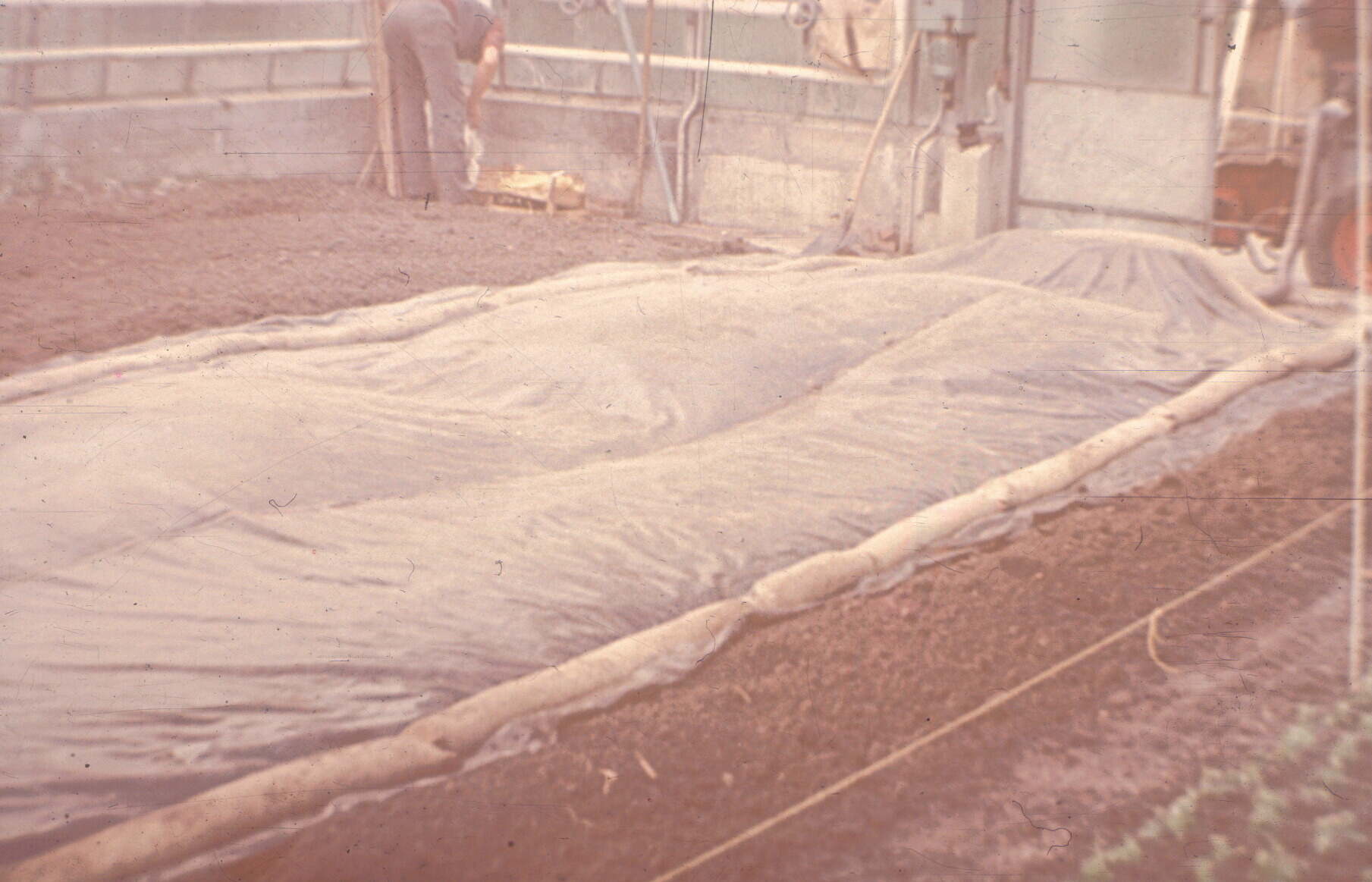
Figure 5.22. Plastic coverage for steaming on the spot
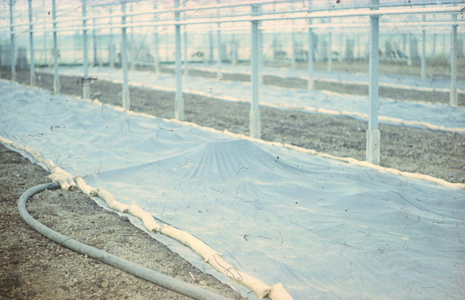
Figure 5.23. Conduction of steam under the plastic cover
Considering the optimal terminal temperature of soil heating, this value should be decreased providing partly the favorable energy use, partly safe working. Therefore, usually a special method is used in which the steam flow sucks air from outside and the titer of mixing can be adjusted to 90 °C as the condensation temperature. The limitation of this method is that the condensate is collected at 30-35 cm depth, so the soil under this depth will not be steamed and sterilized properly. However, for the implementation a sufficient capacity-fixed or mobile-steam generating boiler is needed. In order to choose the proper boiler and calculate the costs of energy consumption the amount of steam needed for the sterilization of a given amount of soil should be determined.
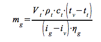 [kg]
[kg]
In which:
ρt - a tt –the density of the soil at the initial temperature [kg·m-3]
ct - specific water equivalent of the soil[Wh·kg-1·K-1]
tv - terminal steaming temperature of the soil [°C]
iv - specific inner energy (enthalpy) of condensed H2O (condensed for tv terminal steaming temperature)[Wh·kg-1]
ig - specific inner energy of steam conducted into the soil[Wh·kg-1]
ηg - efficiency of steaming (its value is in case of steaming on the spot, in case of steaming in a heap it can be 0,7 )
The value of is mainly influenced by the water content of the soil, since the specific heat capacity of water is the highest in such a 3-phase disperse system. It is therefore preferred to carry out the steaming when its water content is less than 20 % by weight.
Finally, a few words about drum disinfectants, which in turn should be used for more than 20% by weight water content of the soil.. The high water content is necessary because the temperature of the soil heated by the flame of a gas or oil burner in a cylinder with slanting axis will not be higher than 100 °C till the water is present in liquid form. The rev of the drum should not be changed, but the slanting of the axis can be modified and consequently the time of soil being in the drum can also be adjusted. During the determination of the time of this treatment it should be taken into consideration that the water content of the outgoing soil can only slightly reduce, vaporize.. Independently of this, to disinfect one cubic meter soil by this method requires more energy than any other soil steaming (heating) processes for the same amount of soil..
Checking questions:
- What kind of relationship exists between average droplet diameter, coverage and dose?
- Describe the drop production methods used in spraying!
- Describe the technical solutions of soil steaming!
![]()
![]()

Hírek/News
Sajtóközlemény
A projekt célja magyar és angol nyelvű digitális tananyagok fejlesztése a Budapesti Corvinus Egyetem Kertészettudományi Karának hét tanszékén. Az összesen 14 tananyag (hét magyar, hét angol) a kertészmérnök Msc szak és a multiple degree képzés keretében kerül felhasználásra. A digitális tartalmak az Egyetem e-learning keretrendszerével kompatibilis formában készülnek el.
BővebbenSikeres pályázat
A projekt célja magyar és angol nyelvű digitális tananyagok fejlesztése a Budapesti Corvinus Egyetem Kertészettudományi Karának hét tanszékén. Az összesen 14 tananyag (hét magyar, hét angol) a kertészmérnök Msc szak és a multiple degree képzés keretében kerül felhasználásra. A digitális tartalmak az Egyetem e-learning keretrendszerével kompatibilis formában készülnek el.
A tananyagok az Új Széchenyi Terv Társadalmi Megújulás Operatív Program támogatásával készülnek.
TÁMOP-4.1.2.A/1-11/1-2011-0028
Félidő
A pályázat felidejére elkészültek a lektorált tananyagok, amelyek feltöltése folyamatban van.
![]() TÁMOP-4.1.2.A/1-11/1-2011-0028
TÁMOP-4.1.2.A/1-11/1-2011-0028