Cutting tools and machines in horticultural practice
6. Cutting tools and machines in horticultural practice
The cutting tools and machines which will be discussed in this chapter are ( Figure 6.1) the
-
Seizers
-
Pruner shears
-
Rotating knives
-
Cutter bars
-
Disc saws
-
Chain saws
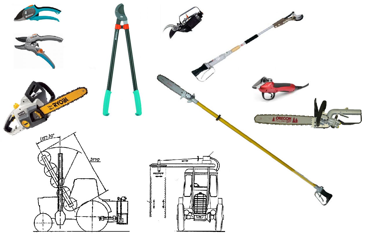
Figure 6.1 Pruning and cutting tools and machines The most commonly used in horticulture
6.1 Classification of cutting tools
Parts or whole plants can be cut - without counter blade - with counter blade
According the direction of cut we can distinguish between
- pure and
- sliding cut
The process of cut is composed of two parts:
0-1. compression,
1-2. the blade moves through the material (Figure 6.2)
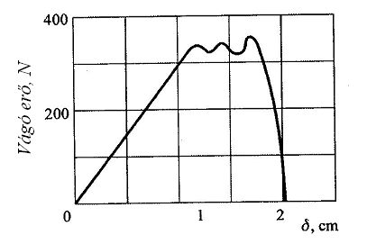
Figure 6.2 Change of cutting force during the cut of the stem
(Szendrő P. 2000)
Let’s study the forces acting during cut (Figure 6.3). The cutting force balances the normal resistance force (N) and the friction force ( T): Fc= N.cos λ+T. sinλ
Because T= μ.N, after replacing: Fc= N(cos λ+ μ. sin λ)
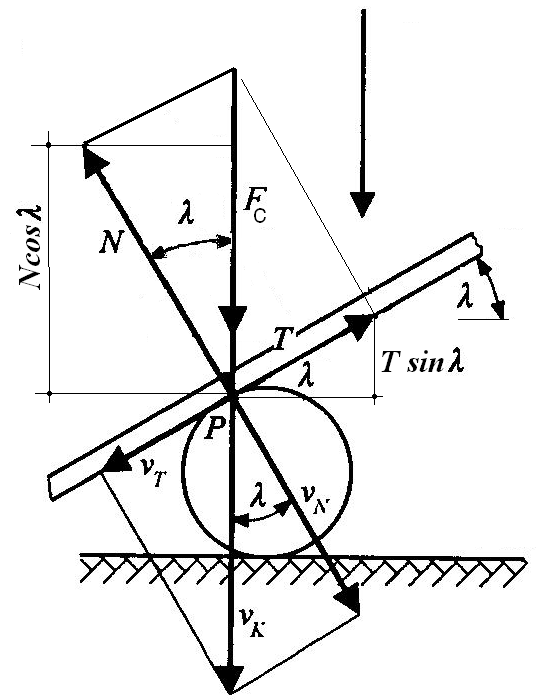
Figure 6.3 Force and speed components on the blade of knife at sliding cut
(Szendrő P. 2000)
Figure 6.3 shows the speed components of the cut as well. At cutting speed vk the speed component perpendicular to the blade is vN and the component parallel to the edge is vγ .
6.1.1 Cut without counter blade
The precondition for the successful cut without counter blade is that the awaking reaction force surpasses the force needed to cot through the object. In the case of grass/grain cutting the reaction force is composed of
-
The inertia force of the stem
-
The bending reaction force of the stem
-
The pulling stress of the stem
-
The backup of other stems
The differential equation of the equilibrium:
F(δ)=Δm . (d 2 x/dt 2 )+F bend (x)+F tens (x)+ F back (x)
where: F the force needed to cot through the object (N)
δ the displacement of knife in the stem (m)
Δm reduced mass of the stem to the knife (kg)
x displacement of the stem (m)
t time since the beginning of the process (s)
F bend bending resistance of the stem (N)
F tens resistance due to the tensile stress of stem (N)
F back backup force of the neighbouring stems (N)
The reaction force due to the bending of stems can be calculated as follows:
F bend = 3.I.E.x/h3
where: I the stem’s momentum of inertia (m4),
E modulus of elasticity (Pa),
h height of cut from ground (m)
Reaction force due to stem pulling can be explained according the right side drawing in Figure 6.4. The blade runs at the height h above soil after starting the cut of the stem. For this the length of the stem must be increased by Δh which arises the tensile force F. The tensile stress is:
σ= F/A, from which the tensile force:
F =A . E . Δh/h
where: A is the cross section of the stem
The reaction force, according the Fig. 6.4 is the horizontal component of F:
F n = F.sinα
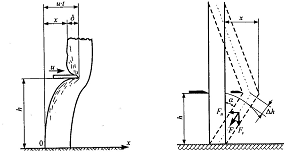
Figure 6.4.. Elements of the differential equation of the cut without counter blade
(Szendrő P. 2000)
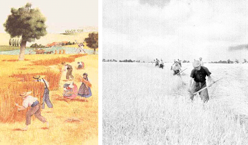
Figure 6.5 Scythes and hooks are tools cutting without counter blade
The most important of the reaction forces during free cut is the inertia force which is in correlation with the speed of the knife. For a good quality cutting a speed of 20-30 m/s is needed.
Most of the rotary mowers, as well as scythes and hooks are cutting without counter blade.
6.1.2 Cut with counter blade
Tools cutting with counter blade have a second knife or bar which serves as backup.
That's why the speed of cutting has not to be high. In the case of advancing mower machines the only requirement is that no uncut area must left behind.
Typical cutting tools and machines with counter blade are
-
scissors,
-
shears
-
pruners and
-
cutter bars
Pure and sliding cut
We may distinguish between pure and sliding cut. At pure cutting the knife moves only perpendicular to its edge. At sliding cut the knife moves both perpendicular and parallel to its edge.
According experience sliding cut needs less force and results in undistorted cut surface. Doesn’t it contradict to the low of energy conservation? No, because, proved by experiences
- at pure cut the force needed is higher, but the path length of knife is shorter,
- at sliding cut the force needed is less, the path length of knife is longer (Figure. 6.6)
As a result of those the energy consumed during the cut is much the same:
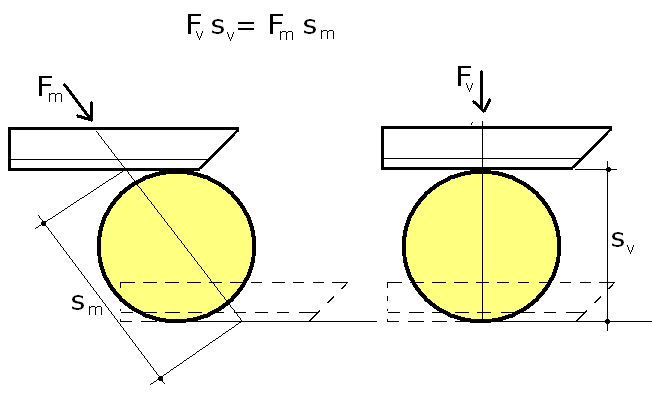
Figure 6.6 The energy consumed during pure and sliding cut
Why is the force at sliding cut less? Because the edge of the knife at sliding cut is sharper.
The reason of sharper edge at sliding cut may be explained on the Figure 6.7. The direction of sliding cutting is shown in red. The angle of the cutting edge at pure cut is α, at sliding cut α’. It is clear that α’< α, which means the edge is sharper in the second case.
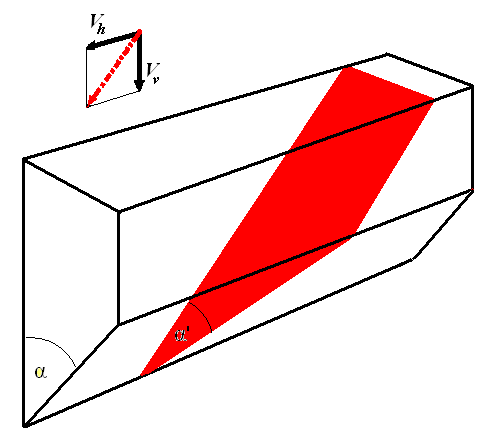
Figure 6.7 The angle of the cutting edge at pure cut and sliding cut
In most of the cases we apply sliding cut. But there are exceptions. In those cases when the friction or adhesion brakes the motion of the edge in the material, the pure cut is the better solution (the edge should pass through the material the shortest way). Examples from the every day’s practice: butter and cheese.
Classification of scissors/shears according the shape of blades and the position of pivot relative to the edges can be carried out as follows (Figure 6.8):
-
Strait edged - symmetric, edges without eccentricity (1)
- symmetric, eccentric edges (2)
- asymmetric, eccentric edges (3)
-
Curved edged - asymmetric, eccentric, log. spiral edges (4)
- asymmetric, eccentric, Archimedes spiral edges
- asymmetric, eccentric, evolve edges
- asymmetric, eccentric, arc edges
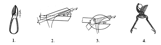
Figure 6.8 Classification of scissors/shears according the shape of blades and the position of pivot relative to the edges
Classification of scissors/shears according their mode of operation:
-
Hand operated
-
pruners : till ø 20 mm
-
loppers: till ø 30 mm
-
-
Pneumatic pruners
-
Hydraulic pruners
-
Electric pruners
6.2 Types of cutting tools
6.2.1 Pruning shears
Hand operated pruners can be distinguished according the type of cutting (Figure 6.9):
-
Bypass: recommended for “life” woody materials
-
Anvil: recommended for dry, “dead woody materials
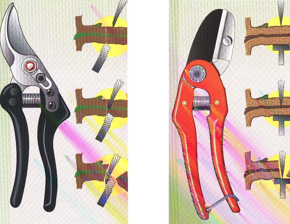
Figure 6.9 Bypass and anvil pruning shear
The force balance during cut can be studied on Figure 6.10. In permanent work the human’s hand is able to effort 200 N. The specific cut resistance of the brunches is 400 N for each cm of diameter (O’Brien at al.1983).
With these data and with the geometry of the pruner the balance of moments during the cut is
F . 12=N.3 (Ncm)
Where F=200 N, the hand force
N is the force on the blade, N
Expressing the force on the blade: N =F.12/3=.200.12/3=800 N
According this, the hand force is able to cut branches of d=800/400(N/N/cm)= 2 cm in diameter.
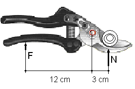
Figure 6.10 Force balance on the pruner
Priority at the design of pruner shears is the reduction of force needed to the cut. The force on the blade can be influenced by
-
Reducing the distance between pivot and branch
-
Increasing the sliding of the blade in the cut object
a.) Leaving the hand force unchanged, with the decrease of distance b between pivot and branch, the force on the blade increases (F.a=N.b). This can be achieved best by using asymmetric, eccentric blades (Figure 6.11).
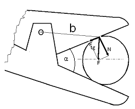
Figure 6.11 The distance b between branch and pivot
b.) Increasing the sliding of the blade in the cut object
To understand the effect of sliding let’s study the displacement of the edges in the cut object (Figure 6.12). The intersection A on the top blade moves in direction S. Dissolving the displacement vector into a component perpendicular and parallel to the edge, the sliding part becomes clear (Stg). The greater the angle α , the greater the sliding effect compared to the pure cut portion.
6.12 The effect of the angle α on the sliding cut
From the other hand α can be increased only until the brunch doesn’t slides out of the blades.
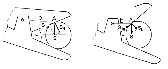
The sliding out is braked by the friction between edge and branch. The part A in Figure 6.13 shows the normal and friction forces on the edges of blades. The resultant force on both edges is R, the resultant force of the two R is E. Part B shows the case when the resultant force E pulls the branch out of the blades.
Decreasing α, the force E decreases as well. On part C the forces R neutralize each other, their result is zero. This leads to E=0. The angle α belonging to this situation is the maximal one, at witch the branch doesn’t slides out of the blades. This angle is at the same time the optimal one regarding sliding cut. At straight edged shears with pivot the sliding effect decreases further with the closure of edges.
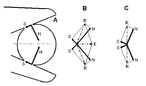
Figure 6.13 The change of normal and frictional forces whit the change of α
.
At curved edge pruners – due to the appropriate design of the curves – the angle between the blades remains optimal during the whole cut (Figure 6.14).
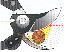
Figure 6.14 The unchanged angle α at curved edge pruners
Pneumatic pruning shears
Handcraft is replaced here by the energy of high pressure air.
The main parts of a pneumatic pruner system are (Figure 6.15):
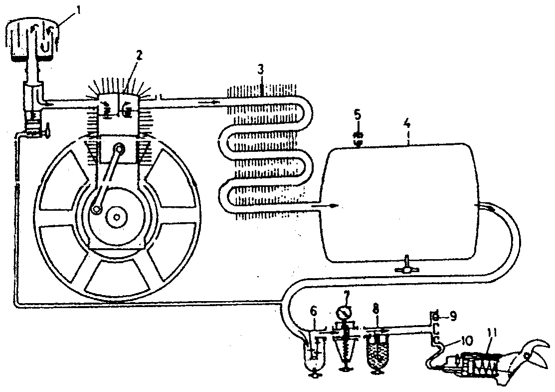
Figure 6.15 Main parts of the pneumatic pruning system
-
air filter
-
compressor
-
air cooler
-
high pressure air tank
-
safety-valve
-
water separator
-
pressure reducer and
manometer
-
oiler
-
distributor pipe
-
flexible hose
-
pruning shear
Construction of pneumatic pruning shears
The grip of the pruner builds a cylinder with a piston in it. The piston is connected to the moving blade of the shear from one side and is driven by the high pressure air from the other side. A hand operated valve lets the high pressure air in the cylinder when pressed. Upon
release the air gets out of it in the surrounding, and the piston with the blade gets back in their original position due to the spring force(see in the Figure 6.16).
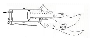
Figure 6.16 The pneumatic pruning shear
The force on the blades is determined by the air pressure, the diameter of the piston and by the mechanical transmission between piston and blade. The usual pressure range for pneumatic driven tools is 0,8-1,2 MPa. The diameter of the piston is limited by the human hand. All these result in about 25 mm cut diameter of the shear.
Using two pistons the piston force can be doubled (Figure 6.17). Note that the cylinder here is separated into two parts, each of them is supplied separately with high pressure air. This way the cutting force can be nearly doubled.
Figure 6.18 shows both the total pneumatic pruning system and its pruning shear.
Figure 6.17 Pneumatic pruning shear with two pistons
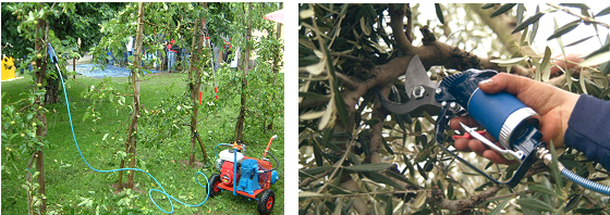
Figure 6.18 Pneumatic pruning system and a pruning shear
The advantages of the pneumatic pruner systems are
-
fast cut
-
light shears
-
one, lightweight hose only
The disadvantages:
-
frost sensitivity, even above 0 centigrade
-
low cut force
Hydraulic pruning shears
Their function is similar to the pneumatic shears, only the power comes here from the energy of high pressure fluid (Figure 6.19). The higher pressure range (1,2- 7 MPa) leads to larges branch cut diameters. This system needs two hoses which are arranged according the "hose within- a-hose" concept.
Advantages of the hydraulic system:
-
no frost risk
-
large cut force
Disadvantages:
-
slower cut
-
heavier shears and hoses (two pipes, each of them filled with fluid)
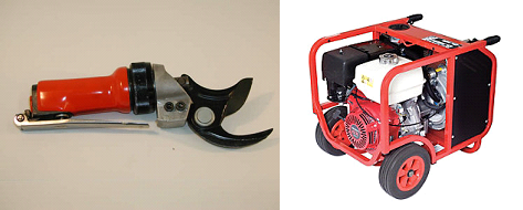
Figure 6.19 Hydraulic pruning shears and its energy supplying unit
Both hydraulic and pneumatic systems can be used for driving other tools, like chainsaw or limb shaker. Figure 6.20 shows choice of tools for the pneumatic system.
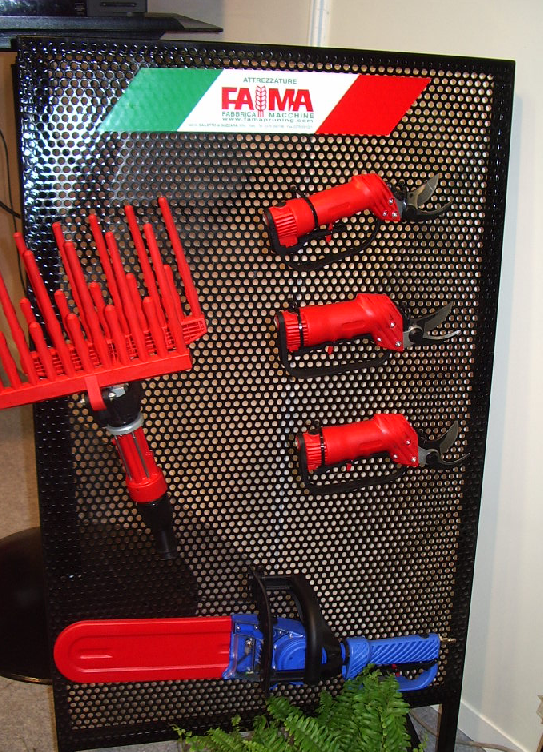
Figure 6.20 Choice of tools for a pneumatic pruning system
Electronic pruners
Electronic pruners are powered by an electric battery pack that is worn around the waist. Battery and pruner are connected by a 1 m long cord (Figure 6.21).
An all-day battery works for 8-10 hours and weighs 2-4 kg. Electronic pruners respond to increased squeeze pressure on the trigger. Uniform powerful cuts leave smooth clean edges that heal rapidly, even on large diameter stock up to 3.0-4.5 cm (Video 6.22).
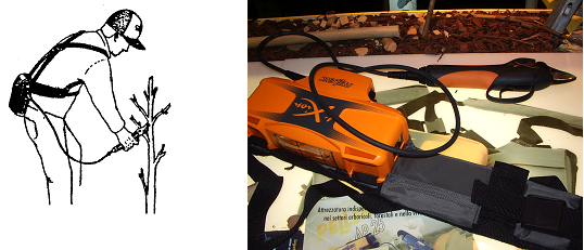
Figure 6.21 Electronic pruner and its battery pack
Advantages of the electronic pruners: they enable individual work. Disadvantages are the high price (about USD 1500) and its heavy weight.
Several well known manufacturers offer both corded and cordless electronic pruners. In the last case the battery is incorporated into the grip and is less long-lasting (Figure 6.23).

Figure 6.23 Cordless electronic pruner
The Table 6.1 summarises some important data of pruners
Table 6.1 Comparison of some data of different pruners
|
Pruner powered by |
Cut diameter (mm) |
Mass of the pruner (g) |
|
Hand |
20 |
200-300 |
|
Electronic |
30-45 |
900 |
|
Pneumatic |
30 |
700-750 |
|
Hydraulic |
50 |
900 |
6.2.2 Mowers
Tractor mounted reciprocating movers with double knife cutter bar are used for polling fruit and grape plantations. (Read in details in chapter 10).
6.2.3 Circular saw pruner
The circular saws are forming one cutting edge, the position of which can be modified by the primer and secondary frames (Figure 6.24). They are mainly used in orchards for topping and for forming vertical canopy.
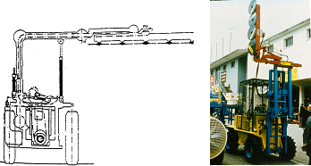
Figure 6.24 Circular saw pruner
6.3 Machines for collecting and handling pruning and woody residues
The possible technologies for collecting and handling residues:
-
Local mulching or chipping than turning it into the soil
-
Harvesting (picking up), chipping and transporting the chips to the
stocking plant and burning the chips
-
Harvesting by round baler, stocking the bales, chipping and burn
them directly or after pelleting them
-
Collecting and transporting the residues to a storage area where it
gets decomposed
In Hungary we can count wit approximately 250 000 tonnes of vineyard pruning and 300 000 tonnes of woody residues from orchards. Their heat value is about 2.5 kWh/kg (compared with 11.6 kWh/kg of fuel oil).
The energy used in all the processing chain is approximately 12% of total energy obtained by burning the chips or pellet. The remaining 88% represents the renewable energy quote, so the process is economic.
6.3.1 Local mulching, than turning into the soil
The residues are first swept in the middle of the orchard/vineyard row, than the mulching follows (Figure 6.25).
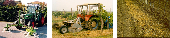
Figure 6.25 Sweeper and mulcher as well as the chips left behind
Mulchers are built either with vertical or horizontal axle
Vertical axle mulchers are supplied with flail knives with (II.) or without (I.) counter- blades (Figure 6.26).
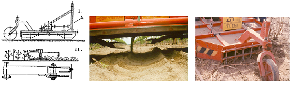
Figure 6.26 Vertical axle mulcher with flail knives
Horizontal axle mulchers
Different types of flail knives are connected to the rotating axle for different diameter of residues: the larger the sizes the heavier tools are needed. Some manufactures offer mulchers with counter-blades
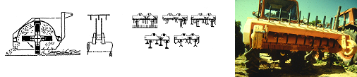
Figure 6.27 Horizontal axle mulcher with different flail knives
The rake teeth on the back of the machines have to retain large pieces.
Chipping locally can be carried out by using tractor mounted pick up chipper. The knives of the rotating chopper drum cut with counter blades. The length of the chips can be regulated by changing the speed of the drum (Figure 6.28).
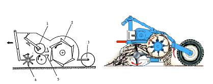
Figure 6.28 Tractor mounted pick up chipper
-
Feed rollers, 2. Chopping rotor, 3. Support wheel, 4. Pick-up finger wheel, 5. Counter-blade
The machine lays the chopped residues on the ground. The following step is the turning of the chips into the soil by a rotary cultivator.
6.3.2 Harvesting (picking up), chopping and transporting the chips in one step
For the picking up and chopping of residues rotating chopper drum with counter-blades are used here as well. In this technology however the drum forwards the chops into a trailer (Figure 6.29).
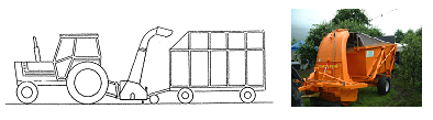
Figure 6.29 Picking up, chopping and transporting the chips in one step
6.3.3 Use of round balers
For the harvest of residues by round baler, special reinforced machines are used. This
balers are now available on the market in great variety. All of them are of crimping roller types (Figure 6.30).
The transport of bales is much more economic compared to the transport of loos woody residues.
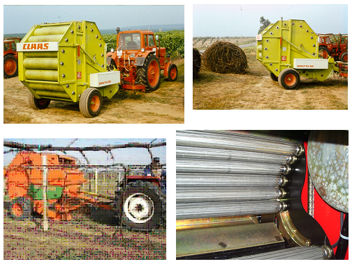
Figure 6.30 Special reinforced balers for the harvest of orchard and vineyard residues
6.3.4 Collecting and transporting without chopping
For collecting the woody residues and transporting them to a storage area without chopping
a special tractor-mounted fork can be is used (Figure 6.31). The fork is connected to the tree point linkage of the tractor. The tractor collects the pruning in reverse, then lifts and closes the fork and transport the mass to the storage area. These steps must be repeated several times until the row is emptied.
References
Szendrő P. szerk. 2000. Mezőgazdasági gépszerkezettan, Mezőgazdasági Szaktudás Kiadó, Budapest, 342-356
O’Brian, M., Cargill, B.F., Fridley, R.B. 1983. Harvesting and handling fruits and nuts. AVI Publishing Company,, Westport, Connecticut, 162-166.
![]()
![]()

Hírek/News
Sajtóközlemény
A projekt célja magyar és angol nyelvű digitális tananyagok fejlesztése a Budapesti Corvinus Egyetem Kertészettudományi Karának hét tanszékén. Az összesen 14 tananyag (hét magyar, hét angol) a kertészmérnök Msc szak és a multiple degree képzés keretében kerül felhasználásra. A digitális tartalmak az Egyetem e-learning keretrendszerével kompatibilis formában készülnek el.
BővebbenSikeres pályázat
A projekt célja magyar és angol nyelvű digitális tananyagok fejlesztése a Budapesti Corvinus Egyetem Kertészettudományi Karának hét tanszékén. Az összesen 14 tananyag (hét magyar, hét angol) a kertészmérnök Msc szak és a multiple degree képzés keretében kerül felhasználásra. A digitális tartalmak az Egyetem e-learning keretrendszerével kompatibilis formában készülnek el.
A tananyagok az Új Széchenyi Terv Társadalmi Megújulás Operatív Program támogatásával készülnek.
TÁMOP-4.1.2.A/1-11/1-2011-0028
Félidő
A pályázat felidejére elkészültek a lektorált tananyagok, amelyek feltöltése folyamatban van.
![]() TÁMOP-4.1.2.A/1-11/1-2011-0028
TÁMOP-4.1.2.A/1-11/1-2011-0028